| Copyright
©2001-2022 Tuner Information Center. Permission is hereby
granted to quote our text so long as proper credit is given.
eBay listings that quote us incorrectly or without credit may be
terminated without notice. This site contains affiliate links for which we may be compensated.
Jim and Bob's DIY Mods
For those interested in modifying tuner audio sections, this page offers some general suggestions, followed by specific information relating to many popular vintage tuners. We started with Kenwoods and branched out from there!
General DIY Tips | More General Tips | Denon TU-460 | Denon TU-660 | Denon TU-800 | Denon TU-850 | Harman/Kardon Citation 18 | Kenwood 600T | Kenwood KT-615 | Kenwood KT-815 | Kenwood KT-880D | Kenwood KT-917 | Kenwood KT-1100SD | Kenwood KT-3050 | Kenwood KT-5020 | Kenwood KT-5500 | Kenwood KT-6500 | Kenwood KT-7300 | Kenwood KT-7500/7550 | Kenwood KT-8300 | Marantz ST6000 | Mitsubishi DA-F20 | Philips AH673 | Pioneer F-90 | Realistic TM-1001 | Sansui T-60 | Sansui T-80 | Sansui TU-217/317/417 | Sansui TU-517/717 | Sansui TU-719 | Sansui TU-919 | Sansui TU-9900 | Sansui TU-D99X | Sansui TU-X701 | Sony ST-4950 | Sony ST-A6B | Yamaha T-85
General DIY Tips
1. Return ground path - On the Kenwood KT-7500, there is a way to help ensure the integrity of the return ground path. There are four screws that clamp the circuit board to the steel frame, which holds the power transformer and more. Loose screws can cause electrical problems in the KT-7500 and other tuners. First, remove the screws and inspect the board and frame for corrosion or dirt. Second, clean the interface with Caig DeoxIT or another commercial electrical contact cleaner. When reinstalling the screws, don't re-tighten them so much as to crack the circuit board - just good and firm.
2. Power supply - Raise the transformer off the chassis with rubber grommets. Measure AC on chassis to outlet gnd with plug oriented both ways, mark plug for lowest noise. New "low noise" diodes, with snubber circuits, bigger better electrolytic caps with smaller bypass caps. Dedicated regulators for audio/mpx sections if you are really going all out. AC power noise filters will also help, either internal or external.
3. Audio section signal routing - Bypass the external de-emphasis switches on the back panel. Direct wire them on the board. Bypass muting relays, switches, board traces, old internal wiring, etc. In the KT-7500 (described below), the audio signal went through two switches, a relay, long board traces, around the power transformer, and then to the RCA jacks. This was all bypassed, and instead CAT5 teflon twisted pair (one wire grounded at one end for shield) was used to go direct from the op-amp output, through 100-ohm resistor, to the fixed RCA jacks. This change alone was responsible for a huge increase in resolution in the mid and high frequencies. Note: you lose muting, but it's worth it.
4. Op-amp mods - Typical stuff, replace stock op-amp with new high performance unit (i.e., BB OPA2604, OPA2132, etc.) Gold plated socket allows swapping. Add local decoupling caps to gnd on +/- rails (many tuner have no decoupling at all).
5. Coupling cap mods - Many small electrolytic caps are in the audio signal path. Replace these with either Black Gate N or NX, NH non-polar electrolytics (Michael Percy) for large sizes (47 µF) and/or use polypropylene caps such as Hovland, Auricap, or Solen (less expensive) for 1-10 µF values. Note that you really need a schematic to find these easily. In many cases, you'll find a very small DC offset out of the op-amp. If your preamp can tolerate say 20 mV DC (mine easily can), then bypass (pull signal from in front of) the coupling cap after the op-amp, usually a 47 µF or larger. The best cap is always no cap! Lastly, you can add a 5K or thereabouts resistor from - rail to output which will bias the op-amp into class A operation.
If the tuner has both fixed and variable outputs, you can do the wiring mods in such a way as to be able to still use the variable output with muting, and use this for tuning stations, then use the direct output for listening. This will use an additional input on your preamp, though.
These mods can be done in a long evening or weekend if you take it slow, and make a HUGE difference in the sound of most '70s era vintage tuners. Here's one case study, as told by Jim:
Kenwood KT-7500/7550 search eBay
"The KT-7500 and 7550 are particularly suitable for modification because there's easy access above and below the chassis, lots of room inside, a good design, and they can be bought at reasonable cost in the used market. Their weaknesses can be improved as described below, and we hope technically oriented readers will write in with even more suggestions.
(1) The first thing I saw inside that needed changing was 120-volt AC on the same circuit board as the RF circuitry. I moved the fuse to the back panel, lifted ALL AC wires with 120-volt potential off the circuit board, and placed them on standoffs next to the power transformer. On some KT-7500s that I've worked on, the power transformer is switchable between 120 and 240 volts. As far as I know, all KT-7550s came this way. If you have one of these dual-voltage models, several wires for 220-240 volts can be tied together when only 120 volts is required. Tie the yellow and white wires together for the return and tie the red and blue wires together for the hot. This configuration usually leaves the least standing voltage on the chassis. Measure both directions before permanently hooking down your polarized cord.
(2) I added John Camille's "snubber" circuit after the fuse and before the transformer. The snubber circuit consists of two 10-ohm, 5-watt resistors in series with the AC wires. One resistor is in series with the hot and one with the neutral. On each side of the resistors and strapped between them are two .01 µF 250V AC or higher disc capacitors. Don't use some generic film cap -- it must be AC power line mains rated and approved (X1, X2 or Y2, 250V AC or more) meeting IEC 60384-14 or EN 132400. Next raise the power transformer 1/2 inch off the chassis on INSULATED standoffs so the transformer is not grounded to the chassis. I also replaced the power cord with a heavier gauge polarized cord. I oriented the cord for the least AC leakage, measured from the chassis to ground.
[Editor's Note - Our contributor Don adds a word of caution: "I want to recommend in the strongest possible way that the caps chosen for the snubber circuit be ones that are safety rated for AC mains as stated above. General-purpose ceramic (or film) caps are not suitable for connecting across the AC line. It is possible that they will fail over time and if they do, they can burn up or get hot enough to cause something else to burn. An example of a good ceramic cap to use would be Digikey # BC2361-ND (Vishay VY2 Series) or Mouser # 75-WYO103MCMCF0KR (Vishay WYO Series)."]
(3) Tracing the signal path shows the audio out op-amps go through a relay, switching, a long signal trace around the circuit board, a parallel run alongside the AC(!), then routed to the RCAs out. By tapping off the negative side of C49 and C50, which are the 47 µF 10V op-amp coupling caps, and running with good wire direct to the fixed output, the sound is infinitely improved. Be sure to cut the old path away at the fixed output but not the variable. You lose muting and AM but keep them on the variable out - it's a small price to pay for better sound. I now mute by turning my volume down. With a low DC offset op-amp like the OPA2604, you can bypass these coupling caps. More on that below.
(4) Remove the old audio op-amp at IC6, NJM45580, install an eight-legged socket. I now use an op-amp socket with long legs. Under the circuit board these longer legs can be used to tie the new de-coupling caps very close to the op-amp's negative and positive supply points. These are not part of the original circuit. Using good caps for decoupling at V- and V+ to ground will yield improvements. I now use two 470 µF caps for decoupling. Things are made easier if you unsolder standoffs marked 27, 28 and 30. Standoff 30 is a ground point and a good place to ground the - and + decoupling caps now used at the op-amp. Remember your polarization negative and positive directions when wiring these two caps. Standoffs 27 and 28 are a good point to tap the stereo signal to wire to the RCA output jacks. I add two resistors here before going to the RCA jacks. 100 to 1000 ohm should be fine. Using exotic wire here is fine but can be a pain tapping into the old RCA outs. One simple solution is to reuse the yellow and blue wires already wired to the output jacks. Cut these as close as possible at the point they leave the circuit board, points marked J11 Y and J10 B, pull these two wires out of the wiring harness and tie them to the resistors you've tied to standoffs 27 and 28 (cut to length). Now you can plug in and play your favorite audio op-amp. My favorite is the BB OPA2604.
(5) You can go a step further and run the op-amp in class A, learned here: http://www.
audioasylum.com/audio/tweaks/messages/31076.html. I have this configuration running in class A in my KT-7550 and it sounds great! In the beginning, I used polypropylene caps along the circuit path but they are a major pain to work with. I have since experimented with Black Gates, Sanyo and Nichicon high-quality electrolytic caps with copper leads, all nice-sounding. I've also been able to pull out deeper bass from the KT-7500 with the following changes in cap values along the audio path. Watch your polarities.
(1) C31 - from 47 µF 10V to 100 µF 16V Black Gate
(2) C33 - from 4.7 µF 25V to 22 µF 16V Black Gate
(3) C41 - from 4.7 µF 25V to 22 µF 16V Black Gate
(4) C42 - from 4.7 µF 25V to 22 µF 16V Black Gate
(5) C45 - from .15 disc type? to .47 polypropylene
(6) C46 - from .15 disc type? to .47 polypropylene
(6) DXing performance (selectivity) can be improved by replacing the filters at CF5 and CF4, and maybe CF3 and CF2 also, since all 4 of these filters are engaged when the tuner is in Narrow mode. Leave CF1 intact for best sound quality in Wide mode. I recommend low-loss Murata 150 kHz filters for the replacements (used to be Part No. SFE-10.7MJA-10A, but check the cross references on Murata's site for the current part number). Soldering in 3-legged sockets here makes it easy to swap different filters in and out. Go to Bob's Filter Corner for more on filter mods.
(7) On the KT-7500 you can hardwire the 75 µS de-emphasis directly on the board with two one-inch pieces of wire instead of the switch on the back panel. This eliminates about 20 or more inches of signal travel off the board, through the switch and back to the board. This will be for the U.S. and other areas that require 75 µS instead of 50 µS de-emphasis. For 75 µS add a wire between standoffs 28 and 29 and between standoffs 26 and 27. For 50 µS, no wires are required.
(8) Since my first KT-7500 mod I've tried many experiments. One is adding ferrite beads before and after the power supply. Another is adding damping material around the chassis. And don't forget to tighten those four screws that hold the circuit board to the chassis to ensure ground return path integrity. I use a wet sponge to keep excess solder off my iron's tip for best results. Also, I like to use a toothpick to clear the hole after removing any old part and before trying to insert a new part. Heat solder at the hole, push the toothpick in and wait a few seconds for the heated solder to 'dry'. Always be quick in and out when heating things up on the board, especially around the ICs. jim..."
KT-7500 Power Supply Upgrade
Jim offers this simple power supply upgrade for the Kenwood KT-7500, which may work equally well with similar Kenwood models:
"Feel free to disagree with the values I chose. I was being conservative with these changes. Also, choice of brands and types of parts are a matter of personal opinion and can be discussed in our FMtuners group.
To start, unplug the tuner, remove the top and bottom covers, and stand the tuner on one end.
(1) Remove C78 (220 µF 16V) and C79 (220 µF 25V) and replace with 470 µF 35V to 50V caps. 50V caps won't fit very flat on the board. Be sure to orient the caps for the same polarity as the old ones. Remember we are working with negative and positive voltages in this power supply.
(2) Remove C81 (100 µF 16V) and C82 (100 µF 25V) and replace with 220 µF 35V caps. 50V caps might be a little too tight to fit. Again watch polarity. These two should be marked on the circuit board, probably because they are in the negative voltage section of the power supply.
(3) Remove C80 (1000 µF 25V) and replace with 3300 µF 35-50V caps. A larger cap won't fit under the dial string so buy a cap with - and + leads on the same end of the cap and extend the - lead for the connection below the dial string. Watch your hands and that soldering iron around the dial string! There is some really nasty, sticky glue holding, at least, C78, C79 and C80. Be very careful removing these caps so you don't break anything including traces on the bottom of the board. Did I mention that old glue?
(4) For added reliability and better performance, I now replace all large capacitors around the board including C44 for the signal meter. The total now includes C82, 81, 80, 79, 78, 75, 74, 67, 44, 40, 15 and 14.
(5) I suggest replacing the 4 diodes (D13, 14, 15 and 16) with the Bob-recommended 100V Schottkys. All changes were, IMO, conservative double or triple values, and I changed the bridge diodes just in case the old ones weren't chosen by Kenwood for the higher capacitance charging value of the new caps. These changes gave each tuner a richer, fuller sound from top to bottom.
(6) If you remember section (1) of the first KT-7500/7550 mod (see above), I talked about lowering the stray AC voltage on the chassis. I noticed when working on the third KT-7500 that there is a 2.2 meg ohm (two point two) resistor designated R1. I must have removed it from my 7550 because it wasn't there. I lifted the end of this resistor closest to the front of the chassis so it stands vertical to the circuit board and hooked the open air end of this resistor to the hot side of AC at a point after the snubber circuit. This was done by extending a small insulated wire to the resistor from the AC. The end of the resistor on the circuit board is ground potential. This changed the voltage potential on the chassis from about 30 volts to 7 volts on the two 7500s and to 4.5 volts on my 7550. With the AC plug polarized you get this 7 volts but about 100 volts potential if the AC cord is plugged in "backwards." I stood the resistor vertical, again in order to keep the 120-volt potential off the main circuit board."
Ray's Passive EQ Mod
January 2006: Ray suggests this passive EQ mod for the KT-7500/KT-7550:
(1) Remove Rb56 and Rb57 (3K) and replace each with a 4.7 K ohm resistor.>
(2) Remove Rb58 and Rb59 (100K) and replace each with a .0068 µF polypropylene cap. Parallel upon new 100 K ohm resistors. (Note: This is for North America's 75 µS de-emphasis. For 50 µS de-emphasis, use .0047 µF's in place of the .0068 µF's.)
(3) Remove Cb45 and Cb46 (.15 µF) and replace each with a series connected 1.0 µF polypropylene cap and 10 K ohm resistor. Jim installed this new network under the chassis.
(4) Remove Cb47 and Cb48 (750 pF) and replace each with a polystyrene or polypropylene 100 pF cap.
(5) Remove Cb89 and Cb90 (1500 pF).
(6) If the output wiring has been modified to go direct from the + terminal points of the removed C49 and C50 to the output jacks, then change R62 & R63 from 33K to 18K to reduce the op-amp's gain.
Here are photos of the top and bottom of the finished product.
Read Jim's review of a KT-7550 with most or all of the above mods on the Modified Tuner Report page. Here's a description and some great interior photos of our contributor Mike B.'s mods to his KT-7500, with the help of Bill Ammons.
Kenwood KT-6500
search eBay
February 2003: Bob played with his KT-6500 and discovered that it's a great project for entry-level DIYers. "Over the weekend I did a painstaking alignment on a KT-6500. While in there, I noticed the utter simplicity of the audio stage. If you ignore the redundant last two caps that can be bypassed, there are a grand total of three caps in the total audio stage. Period. It was just too easy to ignore. They were replaced with 22 µF std Black Gates (all had decent DC bias on them). I also noticed that the long audio output PC traces run right past the power supply - ouch. So this was replaced with twisted teflon wire to the RCA jacks. And a 22 µF/1 µF bypass was added to the MPX chip. And as mentioned, the caps after the output filter, with no DC on them, were bypassed. This has no negative impact on muting or any features.
Here are the details on the caps, as indicated on the board - C37, 4.7 µF, in the middle of the board just below two square metal cans. C67, C68, both 1 µF - on the lower right part of the board. Replace these three with 10 µF or 22 µF standard Black Gate caps, 16V or 50V. Short across the leads of caps C69, C70, on the lower left part of the board. For the bypass caps on the HA1196 MPX chip, put the plus lead on pin 1, and the minus lead on pin 8. The values here are not super important - I try to use a small value like .1 or 1 µF, and a larger one in the 22-120 µF range.
After two days of break-in, this one is a new-sounding tuner. Bass is much deeper/tighter, and the midrange improved nicely. Highs smoothed out. These are so easy to do, I think this one has a lot of potential as a 'first mod' machine for those interested in giving it a whirl. It is a handsome tuner, with a nice dial/tuning mechanism, and can be bought with a wood cabinet for almost nothing. Reception is darn good too, with three stock filters, but not super selective. Audiophiles: cheap thrills await you here."
KT-6500 with Tubes
Impossible, you say? Never say never with Jim around:
"The idea of a solid state RF section and tube output stage has been rolling around in my head for quite some time. After seeing all the room inside a Kenwood KT-6500 I decided to go for it, and the results were very satisfying. If my aural memory serves, the sound is between the McIntosh MR 67 and MR 71. It leans more toward the 67 which has more bass bloom and a richer midrange. Please remember all comments come from a certified tubeaholic. The mods below are for the transistor stage only.
(1) Power supply: Old diodes replaced with Schottkys - D6 and D7
(2) C80 470 µF 16V
(3) C82 220 µF 16V
(4) C83 1000 µF 25V
(5) C61 470 µF 16V - All of the above replaced with new caps 20% to 80% larger in capacitance and with higher voltage ratings.
(6) C67, C68, C69, C70 - 1 µF 50V electrolytics replaced with new old stock 1 µF 30V Sprague polypropylene caps (they look like Vitamin Qs).
(7) C37 - 4.7 µF 25V electrolytic replaced with a 5.1 µF 250V polypropylene cap. This cap is before the FM MPX IC 2, HA1196 and after the FM IF IC 1, HA1137W.
(8) This is where the fun began. I used the inexpensive Foreplay tube preamp circuit as the final gain stage and added a fuse holder on the rear to offer some protection to the electronics of both circuits. I've decided to stop here in the description of this installation because any hard core DIYer knows where to go from here and the novice shouldn't try this anyway. Here is a photo of the finished product."
Kenwood KT-5020
search eBay
June 2004: Here's Jim with some mods to the inexpensive Shootout surprise, the Kenwood KT-5020.
We are aware of three versions of this tuner. My DIY'ed version has switchable voltages and de-emphasis, but some do not. Starting with the de-emphasis: For Europe, England and Australia, C102 and C103 are 1000 pF. For Canada and the U.S. C102 and 103 are 1500 pF. For KT-5020s with a switchable de-emphasis, R119 and 120 (2.2 meg ohm) are in circuit for Canada and the U.S. 75 µS and switched (shorted) out for 50 µS. For my North American version, I bypassed the de-emphasis switch and 2-4 inches of signal trace by removing R119 and R120, the 2.2 meg ohm resistors, and replacing with shorting wires. Coming into the MPX chip is a 10 µF 35V cap (C90). I changed it to a 10 µF Black Gate. Leaving the MPX with L and R channels are two 10 µF 35V caps (C101 and C102), which were replaced with 22 µF Black Gates. The originals were 10 µF but I saw no reason not to go to 22 µF starting with C101 and C102. Always observe polarity with these electrolytics.
I cut out the old audio op-amp (IC 12) and cleaned the holes using a soldering iron and toothpicks, to keep them open and clear. Unless you wish to solder a new op-amp in place, add a new socket for the op-amp of your choice and solder that in place. I always finish all other soldering tasks before plugging the new op-amp in. Continuing along the audio circuit, I changed the two 10 µF 35V caps, C107 and C108, to 47 µF Black Gates. Now, the final two coupling caps have virtually no DC offset, so I chose two NP Black Gates, 33 µF NPs to replace the original two 10 µF 35 volt bipolar electrolytics (C111 and C112). Enlarging the capacitance of the caps following the MPX IC was chosen to extend the minus dB rolloff of the bass. I stress again, always observe polarity. On the KT-5020's circuit board, there is a + sign and you will see a small circle intersecting the larger circle where the positive (+) side of the cap inserts. Also, on the NP Black Gates, 33 µF, the longer lead should be considered the positive side even though it's non-polarized.
One final step is to replace C194 10 µF 35V with a 10 µF Black Gate. Do not increase the value of this cap. Also, I cut the rear to fit an IEC connector, and ran two ferrite cores between the AC cable and the power transformer and another ferrite bead between the multiple AC wiring out of the transformer and the board. No power supply changes have been tried at this time. We will update when it's tried and proven. I lifted muting transistors Q41 and Q42 but couldn't live with the harsh noise generated when switching between stations, so they were reattached. I have only tried an OPA2604 so far. Good luck with your projects. jim...
Read Jim's review of this modded KT-5020 on the Modified Tuner Report page.
Kenwood KT-615
search eBay
Here are some ideas for mods to a KT-615, which can be read in conjunction with Peter's KT-815 writeup below since the KT-615 and KT-815 are similar. Take it, Jim:
"The Kenwood KT-615 is an inexpensive tuner that can be had at a fair price on eBay and elsewhere. I've experimented on a couple of them and am very pleased with the results. Most everything here is basic and common to the Kenwood KT-7500 mods. My choice of parts was from my huge collection of metalized polypropylene, polypropylene and oil and other similar caps bought for and collected from projects over the past 15 years. I haven't tried Black Gates and other newer stuff because I have so much already available. All replacement power supply electrolytic caps were new and I won't bother recommending any particular type or brand. Most of you out there know what you like and want.
The power supply first. FIRST: I replaced C103 through C112 with new caps of the same or slightly larger value in capacitance and voltage rating. SECOND: I replaced diodes D12 and D13 with Schottkys and D14 and D15 with µF, 4007s. I installed the diodes after the caps so they would "see" less heat. Please remember to get in and out with that soldering iron quickly. There are transistors in that area that won't appreciate the hot seat either.
Going on to the audio stage, this is where I applied the film caps. You have C57 .01 µF, C54 22 µF 10V, C56 .047 µF, C61 3.3 µF 50V, then C75 and C76 3.3 µF 50V. Again, remember to be quick on and off those solder joints. When you remove some of these caps and resistors you will be very close to some very hard to replace ICs. I also replaced the following resistors with carbon comp. without steel end caps: R46 470 ohm, R134 4.7 K ohm, R69 and R70 - both of these are 3.3 K ohm. After filters FL4 and FL5 at the non-grounded side of R71 and R72, I tapped off the left and right channels and ran shielded long grain copper leads to new RCA output jacks. These were mounted above the original ones. This bypasses AM and the muting transistors for the shortest, cleanest signal path. The original output jacks still provide all stock functions. The original caps in the audio path, except for C56 and C57, have steel leads and all the resistors have steel end caps - not a good way to transfer your audio signal, IMO.
Unlike the KT-7500, the KT-615 has no final audio buffer amp. For that reason, the KT-615 has less gain and may not be able to drive long cables. My cables are 3 feet long and see the high impedence of my tube preamp. I wouldn't know if the sound would be different into the low impedence input of some transistor preamps. After the changes were made, the midrange was much more open and clear sounding. It made me want to sit up and pay attention to the music being played. The highs had much less sibilance than most old stock tuners. I attribute that to replacing the old electrolytics with all quality film caps. The bass is full and somewhat "slower" sounding than my modified KT-7500. Dare I say smooth and tubelike? I think I have to keep both, maybe use the KT-615 for jazz, classical and new age and the KT-7500 for rock and roll, dance/trance and DXing.
I also replaced two of the 4 ceramic filters, CF3 and CF4, with new 150 kHz Murata filters, and ran a newer heavy duty polarized power cord as done in the KT-7500 mod. I did not raise the transformer off the chassis as in the 7500 mod, because this transformer seemed to run hotter and I figured it needs the chassis to help dissipate heat.
Keep that tuner unplugged when you have your hands in there! Good luck and good listening. jim........."
Kenwood KT-815
search eBay
Like the KT-7500, the Kenwood KT-815 can be found for $100 or so on eBay, and its nicely laid out circuit board makes DIY experimentation easy. Peter, our colleague in Sweden, has kindly contributed the following suggested mods for the KT-815. Click here for a short Word document containing only a diagram to accompany this description:
"Only one channel shown, the other is identical. The circuit will provide a short signal path with only one small coupling capacitor (easy to find a good one) as well as 3.3kW drive and load for FL6 and 7 without running hardly any DC current through it.
The two values for the feedback capacitor refers to 50 µS or 75 µS de-emphasis. Crossing "wires" are meant to connect.
The MC34081 op-amp gives a clean rather dynamic sound quality while the AD845 will add some treble clarity. Other op-amps like the AD711 could be tried, but generally avoid all types having bipolar transistor inputs, FET inputs are preferred. Sound quality can even be judged by listening to inter-station noise!
Supply of the op-amp should be properly filtered and decoupled, +/- 13.5V available in the tuner. Supply for the remaining circuit should be separately RC filtered using 33W and 1000 µF in parallel with 0.22 µF or so polypropylene.
Greater clarity could be obtained by rejecting FL6 and 7, if you don´t mind some ultrasonic frequency components (make tape recordings from the tuner outputs and don´t want bias frequency interference). Filters of this type have a way of restricting audio detail and clarity. Output level can be set by changing the 1.5k resistor. Also FL5 can be replaced by a better sounding 100 kHz low pass filter.
It is probably best to build the circuit on a new separate PCB or test board, FL6 and 7 could be unsoldered and reused. If you are critical about stereo separation, a compensating circuit similar to the original one (like VR7 and 8, etc.) could be added.
Other things to do in the tuner are:
Fourfold increase of the values of the following capacitors: C64, C69, C70+ 0.1 µF polypropylene bypass, C73 + 0.1 µF polypropylene bypass, C78+ 0.1 µF polypropylene bypass. Also C74, C86, C87, C88, could need replacement using new components and the pilot canceler VR6 should be adjusted using the proper equipment.
The ceramic IF filters CF1-4 can be replaced (using sockets). CF1-2 should be selected for good audio (measure and listen to several samples) while CF3-4 should be 150 kHz filters selected for good selectivity and low loss. After replacing CF3-4, VR1 should be realigned for correct signal meter readout.
The antenna input balun should be disconnected if you only use the 75-ohm input. Such baluns often steal power enough to lower the sensitivity by 2 dB just by being connected in parallel with the input! While we are at it, why not double the AM sensitivity just by moving one leg of C8 to the other side of R8. Happy tweaking!"
Bob posted the following summary of his own KT-815 suggestions in our FMtuners group:
"I just went through the KT-815 circuit diagram. Here is my analysis of parts to swap out. Please note, this is at your own risk, and only for those that have extensive experience in modding. Degree of difficulty is not beginner, more like intermediate to expert.
1) Line from pulse count detector -
C72 270p - make it polypropelene.
C73 4.7 µF - I would use 10 µF Black Gate, or whatever.
2) MPX Decoder -
C78 220 µF 16V - bypass to gnd cap - this is actually in the audio de-emphasis circuit. I would bypass with 1-2 µF poly cap underneath.
C90, C91 - .22 µF, 50V - look way too small, which may be why bass is lacking. I would go 1 µF poly.
C81, 83 - at de-emphasis switch - remove and wire directly across C80, C82.
3) Op-Amp
C92, C102 - 47 µF, 16V - power rail bypass caps - increase size to 220-330 µF 25V bypass with .1 µF, put on each op-amp separately if possible.
C95, C96 - separation caps - 10 µF, 16V - use 10-22 µF, 16V Black Gate.
4) Output stage
C100, C101 - 3.3 µF, 50V - go with 10 µF 16V Black Gates.
C104, C106 - 10 µF 16V - replace with 22 µF 16V Black Gates.
I would tap off here, after the cap, with teflon wire to the direct output jacks. You could also try a tap off at R127, R128, after the 3.3k resistor, before the filter, and compare sound. This would eliminate the filter, which may or may not be needed. I think it was there for cassette taping."
UPDATE 11/29/14: Our panelist JohnC did some work on his KT-815 in January 2012 that we just unearthed: "The following are the specific things I wanted to address in the mod, along with the usual recap of the power supply, de-coupling, and signal path couplers: regulate the Negative rail in the power supply; upgrade the op-amps in the audio section; and remove all the AC from the main board to address any 'hum fields' it may be generating. The basic mod followed the suggestions on this page for the 615/815/7500, so what you see is the typical power supply, decoupling, signal path recap and a few resistors thrown in for good measure. Raised the trans, threw in a snubber, you know, the usual. To address the specifics, the first two were relatively easy. Bill Ammons can supply both the adjustable negative voltage regulator board and the op-amp adapters which are socketed for Burr Brown OPA604 and similar ICs. You probably want to put in the op-amp adapters before you do the decoupling and signal recap. There are a couple of cap locations that require some lead forming to work around the adapter boards. If you implement both of these changes you can remove/jumper cap C100/101 from the signal path which still leaves C104/105 in circuit. I also pulled FL6/7 out of the signal path.
"To address the board AC, first a little information. On a factory 815 the following conditions exist: Line AC is already off board but transformer secondary AC is still there entering the board at the back left corner, running along the back, right past the de-emphasis caps, which at this point should have been relocated (HINT), the RCA outputs, and parallel with the Audio Out board traces. All within about an inch of each other. It then picks up the power bridge about 3/4 of the way across the rear of the board. The audio signal picks up the board trace at the front right corner, on its trip back to the RCAs. You can see the green reed switch in the pic. That signal trace runs along the right edge of the board all the way to the back right, and turns left towards the RCAs, nicely surrounding two sides of the power supply and then paralleling the secondary AC from the trans on its way to the PS proper.
"What I did was the following: I pulled the bridge (D29), the resistors that feed AC power to the lamps, and the diode (D23) feeding the muting section from the main board, which addressed all the trans. secondary AC on the board. Assembled a Schottky-based bridge, which I wanted to do anyway, put it on a daughter board along with the dropping resistors for the lamps and the diode feeding the mute section, and hung it off the rear chassis panel. Here's a closeup of the board. Since the original AC traces along the back of the board are no longer 'in circuit,' I repurposed them for the DC out of the bridge board and added a couple of jumpers where the old bridge was at D29, which nicely fed the primary caps in the existing PS. Also pulled the buffer caps, C117/118, for the old bridge because they now are not required.
"When you look at the pic for the bridge board, the red wires are AC power in, the green wires are lamp power, the red and black are DC out, and the white is the rectified mute power which runs along the back of the chassis and picks up the board where the diode use to be. It works quite well. The tuner is noticeably quieter. The replacement op-amps and caps address any quibbles about the audio output section. Bass approaches, but not quite equals a KT-7500 after all mods, probably something to do with Ray's passive de-emphasis and the fact that there are still a couple of caps in the 815's signal path. Now it's a very nice listen. I've been living with it for the last couple of weeks as my primary tuner in the shop and at no point did I want to switch back to the 7500.
"It's nice enough that I'm thinking about Rev2 to the bridge board. I got the board installed and after staring at it for way too long, I believe there's enough room to locate the primary power supply filter caps onto the daughter board which, at least in theory, should be quieter. By the way, that little board is really nice in its trace layout. It would be perfect for an output op-amp build -- it's laid out for an IC with plenty of solder pads for each pin. Radio Shack PN 2760159. RFM also pointed out that it's available from MCM, part no. 21-4570."
Kenwood KT-917
search eBay
Thanks to Peter again for the following info:
"Having modified three Kenwood KT-917 tuners and being the happy owner of one of them, this is my favorite! A carefully modified unit will provide audio and DX that is nothing less than excellent. In fact, it is the best audio I have heard from any tuner, very open with lots of "inner detail" with a wide and deep soundstage, outperforming a modified Marantz 10B (I have modified two of these). I also agree that it can be difficult to modify the IF section of the KT-917. Since the original IF filters have high internal loss, two stages of amplification are used between each filter. After some experimentation, I ended up replacing the entire IF section with the SAW filters using a design of my own with 7 selected ceramic filters, the last 4 of which are 110 kHz. Including the first IF filter (which is easily replaced with a better type), there are now all together 8 selected ceramic filters and the number of filters used can be selected. Now transmitters 100 kHz apart [Editor's note: Luckily, we don't have to worry about this in the U.S.] are easily received when all filters are used.
I also designed a new pulse count detector for the KT-917 to get rid of the DC offset and make it possible to provide an audio signal path without any coupling capacitors. The remaining audio circuitry should generally be 'minimized' using good components (like the AD844). To get the reproduction really open and clean, optimum adjustment of the pilot cancel circuit is crucial. The power supply needs the usual treatment of reducing noise and lifting the transformer from 'ground'.
By the way, it pays to check the alignment of the front end. The sensitivity of mine improved 6 dB after realignment! Also, replacing the antenna switch with a proper low loss 75W HF relay helps to some degree and the isolation between the antenna inputs is improved. Using a good power line filter and a selected ferrite bead on the antenna downlead will further optimize the installation."
Kenwood KT-917 and 600T Filters
search eBay for KT-917
search eBay for 600T
Bob spent some time working on a 600T and has some filter tips:
"There are quite a few cans in the IF stage of the 600T, KT-917 and some other top tuners that are single tuned LC filters. These work in conjunction with the ceramic filters and alter the filter shape quite dramatically, so they must also be set correctly to get the best selectivity and sensitivity, and the lowest distortion. My current method involves looking at a 16-bit 100 kHz FFT analyzer and adjusting these cans for lowest distortion, which ends up centering all the filter sections and making them nicely symmetrical, which also yields good selectivity. I started out by simply "peaking" these cans, but found that is not the correct way to go. These can compensate for "lopsided" or off-center ceramics, which is a quite common problem, so it is the composite filter response of all stages added together that is what is important. Doing an IF "sweep" at 10.7 with a network analyzer will also show this nicely."
Kenwood KT-1100SD
search eBay
Some of Peter's mods to the KT-1100SD are described in the main KT-1100SD writeup on our Kenwood review page. Here are some more:
"I have recently been able to dramatically improve the audio quality of this (already modified) synthesizer FM tuner. By increasing the low-pass filter capacitors of the local oscillator varicap control voltage, to 15 µF SCR metallized polypropylene plus a 4.7 nF polypropylene HF bypass (originally just a 10 nF ceramic), and adjusting some other capacitor values in the associated DC amplifier to maintain tuning stability, the audio quality is now up with the very best, and it now sounds very much like my modified KT-917. The wide frequency response, relaxed clarity and see-through ability on live transmissions has to be experienced to be believed, and is far beyond tuners like the KT-8005, KT-7300 or KT-8300 (KT-9900) also when modified. This impression is enhanced by the very silent background and good audio dynamics. Previously the audio signal path was DC coupled by eliminating all coupling capacitors and using AD844 current feedback amplifiers.
But there is a price to be paid in terms of slower automatic tuning. It can now take several seconds when going from one preset station to another depending on the frequency difference, but for manual tuning there is no problem. Also, it was not easy to maintain tuning stability. If the proper capacitor values are not used in the varicap voltage DC amplifier, subsonic oscillation will easily occur at the lower frequencies of the FM band. The irritating muting-while-tuning was previously disabled.
The "Direct Linear Loop Detector" was previously modified using an AD845 operational amplifier in the loop and lowered loop gain to reduce interstation noise and improve audio clarity, and the supply of the detector oscillator changed to a bandgap voltage reference (AD584) with a filter and buffer amplifier (also AD845).
The stereo decoder of the KT-1100SD uses four analog multipliers (NJM4200D) running in parallel and a 38 kHz tone derived from the decoder IC (AN7418S), and by using multiturn separation trimmer potentiometers, one for each IF bandwidth, with careful adjustment the channel separation can be made very high. Actually, at wide IF bandwidths the unwanted channel leakage can be more or less canceled, but at narrow IF bandwidths depending on modulation some small residual third harmonic remains. Altogether, this makes the audible difference between wide and narrow IF bandwidths smaller than with most other tuners I have tested. When receiving a distant station with fading level, the stereo separation is gradually controlled by automatic lowering of the 38 kHz amplitude, which makes the transition from stereo to mono less obvious. Also, the 19 kHz pilot is removed by cancellation, so no extra filter is needed for this purpose."
More General Tips
Peter adds the following general comments:
"I agree with most of what is said on your DIY page. Lifting the transformer from 'ground' and checking the mains polarity is a good (and often neglected) thing to do, especially in Europe with our higher mains voltage. I have done this several times with good results. A properly tuned RC network across the transformer secondary winding (with the highest voltage) will do away with resonances and sometimes even audible transformer hum. Choose the capacitor for good audio: for example, in my modified KT-1100SD, it was possible to detect the difference between a metallized polycarbonate and a metallized polypropylene 2.2 µF capacitor!
In my case, the series RC network is connected across the secondary winding (or combination of windings) with the highest voltage, and should be tuned to match the particular transformer. Any small capacitors on the rectifier diodes should be removed. They just alter the resonant frequency of the secondary winding. Without the RC network, what would happen is that during the AC cycle just as the diodes stop conducting, the transformer secondary is left to itself and triggered to oscillate, typically a damped oscillation of around 100 kHz (corresponding to the resonant frequency of the secondary winding). The transformer would also do its best to put it out on the mains (which does not have a low impedance at high frequencies) but with a higher voltage, where it would spread to other pieces of equipment connected to the mains and so on through transformer interwinding capacitances. All this is prevented by the RC network if designed properly. For some transformers with more secondary winding resistance, a suitable capacitor only can be enough.
On the primary side, I use dedicated power line filters of my own design, one for each piece of equipment. These filters are designed using a special measurement bridge which simulates real world use, and much attention has been given to suppressing resonances which is a common fault with the vast majority of these filters. Such resonances are to blame for many of the comments people have about power line filters.... What you need is filters that do a job on differential as well as common mode mains interference without leaving their own 'signature'."
Kenwood KT-7300 (2/13/05)
search eBay
Here's Jim: "It would be advisable to read through all tuner mods on this page before starting. There are upgrades common to many tuners that don't need to be repeated. Most all the mods for this tuner were addressed working from the back of the tuner. It's a pleasure to work inside a tuner like this with such easy access from top and bottom. The KT-7300 is inexpensive and a good project tuner for novices to 'get their feet wet on.' I started with the power supply board which is, from the rear, to the left of the power transformer. In this tuner, it's marked X00-1660-00. Don't worry about staying too true to my new values. They were all new caps that I had on my work bench. Most were slightly larger than stock. First is a list of parts replaced on the power supply board.
Power supply board #X00-1660-00:
D01 and D02: replace with Schottkys
C3: Replaced 1000 µF 25 volt with 2200 µF 35 volt
C4: Replaced 200 µF 25 volt with 330 µF 50 volt
C5: Replaced 330 µF 16 volt with 330 µF 35 volt
C7: Replaced 100 µF 10 volt with 120 µF 25 volt
C8: Replaced 1000 µF 16 volt with 1500 µF 35 volt
Decoupling caps changed around the larger board #X05-1280-00 were as follows:
C3: Replaced 47 µF 10 volt with 100 µF 25 volt. This cap is for the signal-strength meter.
C14: Replaced 47 µF 16 volt with 82 µF 25 volt
C23: Replaced 100 µF 16 volt with 120 µF 35 volt
C54: Replaced 220 µF 16 volt with 220 µF 25 volt
C55, 56, 59, 60: Replaced these four 47 µF 10 volt with 82 µF 25 volt
C66: Replaced 220 µF 16 volt with 330 µF 50 volt
Coupling caps replaced along the audio path were as follows. These on main board #X05-1280-00. They are listed as the signal flows toward the output.
C16: Replaced 4.7 µF 25 volt with 4.7 µF 20 volt
C45, 46: Replaced 4.7 µF 25 volt with 4.7 µF 20 volt
C48, 49, 50, 51: Replaced these four 1.2 µF film caps with 1.5 µF polypropylene caps
C61, 62, 63, 64: Replaced these four 3.3 µF 25 volt with 4.7 µF 20 volt
I used the hole where the original power cord entered the chassis as a starting point while cutting a hole for a plastic IEC plug, using a nibbler. This saved extra drilling and possibly having an extra hole in the back. It did, however, necessitate having the IEC stand on its side. I always use hard plastic IEC plugs when adding them onto a tuner. The original tuner's metal case and ground circuit were not designed to be connected to power ground, so leave the IEC ground prong unterminated inside the tuner. If you try to use a metal IEC, you automatically ground the chassis. Don't do it. I drilled two holes for new, better-quality RCA jacks. I connected CCC copper signal wire directly onto resistors R73 and R74, on the bottom of the board. Be sure to hook onto these two resistors on the resistor side closest to standoffs 17 and 18, the side closest to the circuit board edge. Wiring directly to the resistors eliminates the audio signal having to go through more solder, signal trace and standoff posts number 17 and 18. Everything makes a difference. Every little attention to detail helps, especially if you are a minimalist like me. Now, the signal path is much shorter, and goes through better wire to better RCA jacks. The old path was 17 inches longer, traveling through tinned wire and through the old level-control pot. This old volume pot was not used again. The new RCAs are insulated from the chassis and the new RCAs' ground was tied to the ground of the old RCAs.
I used new electrolytics. Most PS and decoupling caps were from Tanner Electronics. The polypropylene caps were IC brand from Antique Electronic Supply. The other coupling caps were all Sanyo OS-CON from Parts ConneXion. I was short of Black Gates for this mod. The wire was CCC copper from Chimera Laboratories. The RCAs were high quality from Taiwan. That's it - and a good alignment per TIC's high standards will help even more. jim..."
5/28/09 update: Another contributor named Peter ("pete_electro") adds, "The KT-7300 has a lot of electrolytics in the audio path. These should be replaced, preferably with MKT foil types, as these are small enough to fit on the PCB. The power supply and supply buffering caps can be replaced with slightly bigger capacities and the next higher voltage rating, so you are safe for the next 30 years. The OSCON next to the MPX decoder is a voltage rail buffer. This can be any other quality type, but I guess I was in a kind of OSCON mood. As far as I recall there is an additional cap of 10 µF, soldered directly to the MPX decoder chip on the downside of the PCB. This was replaced with a reasonable Panasonic FC. For voltage buffering of RF and ZF circuits you will find electrolytics and next and inside the circuits ceramics. The electrolytics can surely be replaced with OSCONs, as they have good high frequency characteristics. The addition of an OSCON at the front end was my idea because there is no supply buffer cap in this area, as can be found in other tuners."
Read about the performance of a modded KT-7300 on the Modified Tuner Report page.
Kenwood KT-5500 (3/15/05)
search eBay
Jim calls this one "a nice little inexpensive toy":
"I was commissioned to modify an inexpensive Kenwood KT-5500. Because this tuner can be had cheap, I decided to buy one to practice on because the owner loved his stock one and I didn't want to practice on his. This was my first time inside a KT-5500. The rear panel is plastic so it's easy to cut a hole if you wish to add an IEC plug. I checked for proper polarity using the original plug, marked positions hot and neutral inside the chassis and installed an IEC, followed by the normal snubber circuit. I was given very expensive RCAs to install and it was quite a chore to carefully cut out the stamped RCAs. I would recommend leaving the stock ones in place, especially if you're a novice. I've torn apart countless pieces of audio gear through the years and even managed to put some back together, and it's always a challenge redesigning/reworking some of the cheaper manufactured or stamped parts and panels. The 300-ohm antenna connection was not reworked. I was surprised to see cheap tantalum capacitors in a Kenwood tuner's audio path, but then, this isn't an expensive Kenwood.
I used close to or slightly larger than the original values. Be sure to double-check each capacitor's polarity before final soldering. I always install and solder all the power supply capacitors before replacing the rectifier diodes. Also, I always give adequate cooling time after each solder connection before moving to the next one. This helps prevent cold solder joints and gives time for the heat to dissipate, which is especially important when you are soldering close or next to large ICs and zeners on the board.
The power supply values and changes were as follows:
C49: 100 µF 16 volt changed to 120 µF 35 volt
C50: 220 µF 16 volt changed to 330 µF 35 volt
C51: 470 µF 16 volt changed to 560 µF 35 volt
C52: 1000 µF 25 volt changed to 1500 µF 35 volt
D 6 and D 7 diodes switched to Schottkys. I bent the small voltage AC input terminals to accommodate the larger-than-needed Schottkys.
The decoupling capacitors changed were as follows:
C23: 100 µF 16 volt changed to 120 µF 35 volt
C53: 3.3 µF 25 volt changed to 4.7 µF 35 volt
C37: 100 µF 6.3 volt changed to 100 µF 25 volt
C15: 10 µF 25 volt changed to 22 µF 35 volt
C47 and C 48: Both are 47 µF 10 volt, and I changed to 47 µF 35 volt. Use the same value and type.
The audio path values and changes were as follows:
C14: 4.7 µF 25 volt changed to a 10 µF 63 volt Nichicon MUSE
C45 and C46: The original .1 µF 35 volt tantalums were changed to 3.3 µF 50 volt Black Gates. The results gave me a nice, sonically pleasant sound. Subjective opinions are in the works. jim..."
Kenwood KT-8300
search eBay
Our contributor Mike B.'s KT-8300 was extensively modded by Bill Ammons and Mike, and Mike's website has great interior photos showing the mods. Our panelist JohnC's mods to the KT-8300 can be found with a word search in our FMtuners group, but here's a summary:
"Replace each of the OEM zeners in the PS with a series pair of LM329DZ precision zeners.
Replace the pass transistor in the power supply with a D44VH10, better part.
Don't exceed 0.47 µF at C85, 86, 87, 88. I used polypropylenes there.
Pull the de-emph switch, associated wiring 3000 pF RelCap RTE replacement for the two existing caps per channel.
I believe those are the big points.
I used a 2604 at IC 13 and a 2134 at IC 11. If I remember correctly, a 2604 at IC 11 tends to oscillate, but the 2134 is fine."
Our panelist Bob adds: "You can use an OPA2604 at IC 11 ONLY if you place a small cap in parallel with the negative feedback resistors. This is buried in my earlier FMtuners group messages on the topic. By 'small,' my recall is it needs to be in the 5-10 pF range, but check the messages. You'll know if it oscillates - you'll hear it in stereo mode between 5-9 kHz very clearly."
Realistic TM-1001
search eBay
Our contributor Paul Baptista chimes in with mods to an inexpensive and underrated tuner: "My first eBay experience was the purchase of a Realistic TM-1001 tuner. Why this tuner? I was looking for an analog tuner that I could afford that had the following features: signal-strength meter, multipath meter, wide and narrow bandwidth settings and, of course, analog tuning dial. The only one that popped up was this model. I used the unit with the skinny 300-ohm dipole nailed to the frame of the window. I was finally getting decent FM stereo reception and enjoying some surprisingly good sound quality from a few FM stations that don't modify the music signal too much before they transmit it. But itchy fingers I have, so soon I began thinking about which mods I could do with my soldering iron and voltmeter. RF/IF and filter mods are out of the question without the tools and knowledge. My first obstacle was finding the service manual or schematic for this model. I searched high and wide and finally found a generous soul on the Internet who had painstakingly redrawn the schematic a few years ago and sent me a copy of the file. (I do mean redrawn, in the sense of creating capacitors and resistors from multiple line segments in a drawing tool, since he didn't have access to a schematic capture tool that had a pre-drawn resistor or cap or diode.)
Here is a list of all the modifications I executed. The impact to the sound is described at the end. Many thanks to the FMtuners group and to the TIC web site (I mean the folks of course) for ideas, suggestions, advice and pointers.
1. Inserted rubber grommets between the AC power transformer and the metal chassis.
2. Replaced skinny two-prong power cord with a generic three-conductor power cord. Each conductor is 18 AWG. The third conductor was connected to the chassis at the ground point of R851 near the AC plug.
3. Completely removed the small PCB #0063C that contained the parts for the variable output jacks, R352, R531, VR351a and VR351b, and the two shiny metal RCA jacks and a potentiometer. The output is now fixed level only and is pickoff from stubs at point 46 and point 45 via coax cable using the center conductor of two runs of 22AWG RG-59/U coax. Two new gold plated RCA jacks are panel mounted but isolated from the panel. The RCA jack grounds are tied together and then grounded to the circuit ground at stub #54 via a 22AWG insulated wire.
4. Disconnected the 75-ohm antenna skinny wire input from the circuit since currently I only have a 300-ohm antenna. Soon I'll do the reverse and remove the 300-ohm input from the circuit and move to 75-ohm input instead. Once I get an antenna that allows this. I'll install an F-connector in the hole in the panel left empty by removing the variable output pot (see mod #3 above).
5. Replaced the four hard plastic feet with four soft rubber feet. Made the feet myself from soft rubber discs. Used the original mounting screws.
6. Cleaned out tuning cap, lubricated tuning knob axial and dial cord spindles.
7. Cleaned and polished the aluminium faceplate.
8. Cleaned and polished the walnut veneer exterior.
9. Cleaned the plexiglass display window on both sides and the background frequency numbers and polished the frequency pointer.
10. Taped around the lamps that light up the signal-strength and multipath meters to focus all light to the meters to prevent light from being scattered into the main display window.
11. Changed C223 (22 µF/25V) to a 47 µF Black Gate Std radial.
12. Changed C303 (10 µF/25V) to a 22 µF Black Gate Std radial. C303 and C223 are back to back between pin 2 of LA3350 and pin 6 of HA1137.
13. Changed C316 (0.1 µF/50V) to Solen Fast Cap PPE Series 0.47 µF, physically hard to fit an axial cap here but I managed.
14. Changed C317 (0.1 µF/50V), same as C316. C315 & C316 sit just after the low-pass filters and just before the output transistors.
15. Changed C320 (1 µF/50V) to Solen Fast Cap PPE Series, 1 µF, again an axial of this size is tricky but workable with care.
16. Changed C321 (1 µF/50V), same as C320. C320 & C321 are the last caps before the output jacks.
17. Changed C305 (1 µF/50V) to Solen Fast Cap PPE Series, 1 µF. Here this cap is next to impossible to fit. Good luck! Be creative or find a small cap.
18. Changed C306 (1 µF/50V). Same as C305. C305 & C306 are just before the low pass filters.
19. Changed the bypass cap in the MPX area C302 (1 µF/50v) to a Nichicon Low Impedance Alum Electrolytic 47 µF/63V and further bypassed it with a 0.1 µF/63V Vishay MKT 1826 Series Metallized Polyester Film cap. The Vishay is a tiny flat square cap so it fit on the underside of the PCB.
20. Changed C422 (47 µF/16V) to Nichicon Low Impedance Alum Electrolytic 470 µF/63V.
21. Changed the power supply cap C802 (1000 µF/25V) to Nichicon Low Impedance Alum Electrolytic 2200 µF/63V.
22. Changed the power supply cap C803 (220 µF/25V) to Nichicon Low Impedance Alum Electrolytic 470 µF/63V.
23. Regarding the power supply cap C810 (47 µF/16V) - note that on the schematic C810 and C811 are actually the reverse of what is in the tuner (human error on the schematic diagram). I replaced it with Nichicon Low Impedance Alum Electrolytic 100 µF/63V.
24. The power supply cap C811 (220 µF/16V), see note in #23. Replaced with Nichicon Low Impedance Alum Electrolytic 470 µF/63V.
That's it for now. I would love to get it RF/IF aligned and maybe pop in narrower filters in narrow mode, but I would like get someone in the Montreal area to do it to avoid the shipping costs. I don't want this 4-gang tuner's cost to climb much higher.
What is the result of all this? First off, it provided several hours of relaxing leisure activities... a great hobby especially during the winter months. Second, the unit's total cost is now around $140 CAD, so it's still under $100 USD. And third, much better sound quality. Since I didn't listen to the unit after each mod, I can't say which mods had most impact or less impact. What I can say is this: using the same antenna setup and the unit in the same position, the FM stereo image is wider now. It seems to go beyond the physical position of my loudspeakers. Human voices sound more natural and less "through a tunnel" or nasal. The bass is deeper, or at least more present. The midrange is very enjoyable. Overall it sounds much better - a "night and day" type of difference. Now I can only imagine what it would sound like using an outdoor FM antenna and after a proper RF/IF alignment.
Note: wife-to-be [now wife - Editor] acceptance factor, I quote: "It sounds very good. You will buy something modern, right? A black unit? That wooden box just doesn't look like it is a serious home stereo system for someone who likes audio as much as you do." If only she knew that the valve amp project I'm preparing is going to bring more wood chassis onto the rack and remove the machined aluminium amp that is there now....
Sansui TU-217, TU-317 and TU-417
search eBay for TU-217
search eBay for TU-317
search eBay for TU-417
Here's Jim:
I picked up a Sansui TU-217 to review for the Shootouts. After the review, I thought it would be fun to rebuild. One thought was to try some capacitors besides Black Gates. I bought Nichicon MUSE, listed as an "excellent sounding, budget conscious alternative to Black Gates," and Sanyo Oscon, listed as "feature film cap type frequency characteristics, ultra-low ESR." Both brands feature copper leads, like Black Gates. To say they equal or better Black Gates would require rebuilding two of the same model tuner, and A/Bing them with both having good alignments and matched filters. That probably won't happen, but I can say that after the rebuild I ended up with an excellent-sounding tuner. No real change was perceived in the bass, but a better, more articulate midrange and the slightly forward treble moved back in the sound stage with less sibilance than a stock 217. The overall sound became more balanced, top to bottom, which is one of the keys to the L-02T's magic.
The TU-217 rebuild description below will also apply to the TU-317 and TU-417. All three models are basically the same tuner and circuit design inside with the same circuit board layout, with a few exceptions: the TU-417 has a volume pot and is in a larger case to mimic the more complex TU-517 and 717, and in the 417 C51 and C52 are 10 µF rather than 6.8 µF as in the 217 and 317. The 417 has a beefier power supply, probably because of the larger number of lamps used. Sansui had a good marketing strategy on these five models, expanding their line to five tuners using only two circuit designs.
Power supply, meter supply and wiring used off-the-shelf parts, no real exotics.
D101, 102 with 4007 µF, diodes or Schottkys.
C102 470 µF changed to 1500 µF
C106 220 µF changed to 560 µF
C17 47 µF changed to 100 µF
C28 1 µF to 1 µF
C78 47 µF to 120 µF
C79 47 µFto 120 µF (schematic mistake lists C78 twice)
C43 330 µF to 560 µF
C47 10 µF to 10 µF
C48 10 µF to 10 µF
Audio path - choice caps were chosen:
C34 47 µF to 47 µF - Sanyo Oscon
C35 4.7 µF - Sanyo Oscon
C49 10 µF to 10 µF - Nichicon MUSE
C50 10 µF to 10 µF - Nichicon MUSE
C51 6.8 µF to 10 µF - Nichicon MUSE
C52 6.8 µF to 10 µF - Nichicon MUSE
Listening this morning while going over the schematic, I wondered why I really needed the pair of caps after LPF 01 (caps C51 and C52). C49 and C50 block 4.8 volts DC each, but I saw no DC offset after the LPF. Figuring Sansui didn't put these two caps here just for fun, I tried all switching to get a DC offset pulse. Turning the on/off switch, I was able to get a very quick, short 1 volt spike before C51 and 52, read on a digital VM. It was still there as .4 volts after C51/52, though. I decided to bypass these last two caps. Bypassing C51/52 puts R51/52 in parallel with R53/54, so I lifted R53/54 from ground. I don't recommend strapping out C51/52. It is just an exercise I had to try. I'm listening this way now, and it sounds great. I think it's Ed Hanlon who is a fan of simple 3-gang, 2-filter tuners. For music enjoyment, this one is sure to please, whether before or after a little work. You will need strong signals for less background noise. Have I become a tuner snob? I've owned several TU-217s and TU-317s and one TU-417, but always traded them off thinking they're not good on weak signals, I need a better front end, a more exotic audio stage, etc. - even though I've always been drawn to their clean lines. This time around, I think I should keep at least one under-appreciated Sansui in my collection. jim...
Sansui TU-517 and TU-717
search eBay for TU-517
search eBay for TU-717
Here's Jim again with Sansui TU-517 and TU-717 mods and tweaks:
First rule: Double-check, no, triple-check the polarity of all electrolytics and diodes when installing new ones. RCAs, IECs, coax connectors, cleaning this and that part are a given in most audio circles and need not be rehashed here. All differences between the TU-717 and TU-517, as far as these mods are concerned, will be noted. Starting with the power supply board marked F-2681, I usually change caps with good caps ranging from the stock value to three times as large. Also, be sure to use the stock voltage rating or higher when choosing new caps. I usually keep the same value or go as high as doubling the value of the power supply and decoupling caps. You can go from there per your expertise. Except for C25, I've not listed any caps below the value of 10 µF. Below is a list of parts I replace.
Power supply board #F-2681:
C03, C04: 470 µF 35V - Use the same brand and value in both positions.
C05: 100 µF 25V
C08: 100 µF 10V
C09: 10 µF 25V
C10: 47 µF 16V
Remember that the transistors, zeners and diodes "see" the heat when you change these caps, so good soldering practices need to be observed. I always change the rectifier diodes last in this step. Those are D01 and D02. As in the other mods, use Schottkys or the diode of your choice. Make sure they have a voltage rating of 100V or greater.
Decoupling caps to change around the boards are as follows:
Circuit Board #F-2678 - When reading the schematic left to right, top to bottom:
C24: 100 µF 16V
C34: 33 µF 10V
C50: 10 µF 10V
C82: 10 µF 16V
C100: 47 µF 16V
C101: 47 µF 6.3V
C74: 47 µF 16V
C73: 47 µF 16V
C72: 100 µF 16V
Circuit Board #F-2730 - The one under the metal case.
C18: 100 µF 16V
Circuit Board #F-2680 - The one directly behind the front level control. Be careful removing this little troublemaker. On the first TU-717, I took the entire tuner frame apart! Bob walked me through my second 717, and his method is much safer and easier. You must remove the faceplate, and remove the screws and nut that hold the board and volume control in place. Remove the wiring harness from the twists on the bottom. This gets those wires out of your way. Now lift the string off the small wheel closest to the back of the board to be removed. Then you barely, just barely, have enough room to pull the circuit board from its hole. Now you can replace with new caps. Remember, while it's out and dangling, there are quite a few coupling caps on that board to be replaced also.
C25: 3.3 µF 50V for the 717 and 6.8 µF 50V for the 517. [EDIT: JohnC says "I have a couple of 717s and both had 6.8 µF caps in that location, which I replaced with 10 µF."]
C09 and C10: 33 µF 16V - I replace with the same value or leave alone. Use the same brand and value in both these positions.
C11 and C12: 470 µF 6.3V - Use the same brand and value in both these positions.
C23: 100 µF 16V
Circuit Board #F-2679 - No changes on the TU-517. Change these on the TU-717:
C05: 100 µF 16V
C03: 10 µF 16V
Audio path coupling caps to change around the boards are as follows:
Circuit Board #F-2730
C17: 47 µF 16V - Use the same µF value, audio grade.
C16: 10 µF 16V - Use the same µF value, audio grade.
Circuit Board #F-2678
C71: 3.3 µF 50V in the TU-717 - Replace with one 10 µF, audio grade.
C71 and C122: 4.7 µF 27V in the TU-517 - Replace C71 with one 10 µF, audio grade. Leave C122 blank. These were in parallel.
C75 and C76: 10 µF 25V - Change to 10 to 22 µF, audio grade, both the same.
Circuit Board #F-2680: The troublemaker.
C01 and C02: 1 µF Mylar? - Replace with good film caps (both the same) that will fit, or leave stock. Remember you have to stuff the bad boy back in place!
C13 and C14: 10 µF 25V - Replace with 10 to 22 µF, audio grade, both the same.
C19 and C20: 3.3 µF 10V - Replace with 4.7 to 10 µF, audio grade, both the same.
C21 and C22: 10 µF 25V - Replace with 10 to 22 µF, audio grade, both the same.
And that's it, except for the most important factor: a good alignment with good, matched filters. But that is another story for another page on the TIC. jim...
Sansui T-60
search eBay
Our panelist JohnC (not to be confused with John Camille) played with a Sansui T-60, the little brother of the T-80:
Since this is my first attempt at writing something like this, I read all of Jim and Bob's stuff and tried to follow their format. I got addicted to Sansui tuners after I modded a TU-717 following Jim's recipe. Decided to try something simple so looking at the Sansui list on the TIC I noticed that there was little info on the T-60 and decided to start there. Found one on eBay for $5.00, definite sparrow feed (Ray would be proud), and dove in. What resulted was a pleasant surprise. The T-60 is very easy to work on with access from both top and bottom. Well, here goes. All notations are listed as capacitance/voltage. Please read Jim and Bob's general comments, which are worth their weight in gold. Again double, no triple-check, polarity BEFORE soldering and make sure it's unplugged.
Power Supply: Used Panasonic FMs
C80 470/35 to 1500/35
C83 220/35 to 560/35
C85 220/16 to 560/35
C86 100/16 to 220/25
Diodes DO 6,7,8,9 - replaced with Vishay Telefunken FREDs SF4007s after
cap replacement.
Audio Path: Since there are so few, Black Gate N Series were used. I also tried Nichicon MUSE KZs & ESs with comparable results. Let your wallet be your guide.
C30 and 37 4.7/50 to 10/50
C51 and 52 .22/100 to 4.7/50
C75 is in the AM signal path - 1/50 to 4.7/50
Decoupling Caps: Again Panasonic FM or FC if the value is not available in FMs.
C38 220/16 to 560/35
C20 47/16 to 120/16
C31 10/16 to 10/25
C62 10/50 to 10/50
C72 10/50 to 10/50
C77 10/50 to 10/50
Odds and Ends: Audio output from the board is at the front of the chassis routed through a length of ribbon wire (red/white/blue-white) to the RCAs at the rear. Replacement of this wire with shielded low-noise twin lead made a significant improvement in the sound. I also added an F-connector to the rear directly above the existing antenna connection points. There is plenty of room on the rear panel and the board has an unpopulated solder pad for the lead. This was done more as a convenience than anything else. Lastly, I installed John Camille's snubber before the transformer. This seemed to help on some of the background noise.
The T-60 does not have a switch for de-emphasis but the schematic (at F1) does supply values for the appropriate region with the cap numbers. Since this one was an export model which gives you an adjustable transformer, the de-emphasis was set to "export" values which seems to be somewhere between 50 and 75. Sort of "one size fits all." Correct as appropriate. The single lamp used has the same base as in the TU-519/719/919 and GX000 series receivers, except that it is 20 volt, .12 amp.
Results: My reference here is a modded and aligned TU-717. Obviously the T-60 can't match the T-717 for sensitivity, but it had no trouble grabbing a good signal on a 21 kW college station 45 miles out through a roof-mounted Radio Shack yagi. The sound is smooth in the midrange with well-defined bass. The T-60 doesn't have the high end air/extension that the 717 has, but it images very well with decent depth. It does outperform a 217 with similar mods and attention in most, if not all, areas. A great weekend project with tangible results. -JohnC
Sansui T-80
search eBay
JohnC is back with mods for the Sansui T-80:
The T-80 is the big brother of the T-60. There are additional features, such as a digital frequency readout, noise canceler switch and digitally quartz-locked front end. Internally the T-80 includes an upgraded power supply, and two additional boards to support the quartz lock and the display. The main board is common to both tuners with a slightly different component layout. With sale prices on eBay very close to those of the T-60, the T-80 is the better bang for your buck, IMHO. It also passes the "heavier must be better" audiophile test for quality. Before you start, make sure it's unplugged, especially since the power switch is on the secondary side of the transformer, and double-check cap polarity before power-up when you're done.
All notations are listed as capacitance/voltage
Board: F-3130
Power Supply: Used Panasonic FMs
C80: 470/35 to 1200/35
C78: 470/35 to 1200/35
C83: 220/35 to 560/35
C85: 220/16 to 560/35
C86: 100/16 to 220/35 (see "Second Thoughts")
C81: 100/16 to 220/35
C82: 10/50 to 22/50
C84: 10/50 to 22/50
Diodes DO 6, 7, 8 and 9 replaced with Vishay Telefunken FREDs SF4007s after cap replacement (see "Second Thoughts").
Audio Path: Since there are so few caps in the audio path, Black Gate Ns were used. I also tried Nichi KZ and ESs with comparable results. Let your wallet be your guide.
C30 and C37: 4.7/50 to 10/50
C51 and C52: .22/100 to 4.7/50
C75 (in the AM signal path): 1/50 to 4.7/50
Decoupling Caps: Again Panasonic FM or FC if the value is not available in FMs.
C38: 220/16 to 680/25. Double-check the height because it has to clear the digital display board.
C11: 220/16 to 680/25
C20: 47/16 to 120/16
C62: 10/50 to 22/50
C72: 10/50 to 22/50
Board F-3000 (digital display section) - since it has to be removed to access an area of F-3130, and if you're an incurable solder slinger. I used Nichicon MUSE ES but Panasonic SU are fine.
C52: 33/16 bipolar to 100/16 bipolar
C53: 3.3/16 bipolar to 4.7/16 bipolar
C54: 22/10 bipolar to 33/16 bipolar
C22: 33/16 to 47/25 polarized Panasonic FM
C26: 33/16 to 47/25 polarized Panasonic FM
Odds and Ends: Audio output from the board is at the front of the chassis routed through a length of ribbon wire (red/white/blue-white) to the RCAs at the rear. Replacement of this wire with shielded low-noise twin lead (Belden 88641) made a significant improvement in the sound.
Added an F-connector to the rear directly above the existing antenna connection points. There is plenty of room on the rear panel and the board has an unpopulated solder pad for the signal lead. This was done more as a convenience than anything else.
Installed John Camille's snubber circuit before the transformer. This helped to quiet the background noise.
The T-80 does not have a switch for de-emphasis but the schematic (at F1) does supply values for the appropriate region with the cap numbers. Correct as appropriate.
The single lamp used in the T-80 is a 20 volt, 0.12 amp incandescent.
Results: My reference here is a modded and aligned TU-717. If you read the results for the T-60 DIY above, the T-80 shows greater improvement in all these areas and a blacker background behind the program with no downside. Since access to the boards is very easy, the entire mod can be completed in a few hours. Now, if you are really having fun, here's what Ray suggested (from what I understand, this is a Bob Fitzgerald tweak that Ray implemented on his Marantz ST-5 and SAE Two T3U mods):
"Get an Ammons (2) filter adder board. Ask him to put two matched GDT 230 filters in it. When you receive it, pull the input 230 CF and replace it with a .1 µF cap inserted across the outer holes. Put the adder board into the tuner's CF-01 position and put the remaining 230 GDT into CF-02's position. You'll get more IF gain (sensitivity) and reduced distortion through optimized loading and use of GDTs.
The Ammons filter adder board stacks up as: input CF to FET amp to output CF. Bob's mod is to pull the input CF and plug the cap into its socket. This then provides a better load to the IF transformer, some gain and optimum load to the remaining CF. Ceramic filters of the GDT type have improved filter characteristics at the cost of more loss, but the adder board's amp more than makes up for the loss. The modded adder board then replaces the first CF in your tuner. The GDT CF that was pulled from the adder board is then used to replace the second CF in your tuner. You'll have to determine which of the three pins is the input side of CF1 on your tuner's board (the center is always ground) from the schematic and P.C. board layout. Ammons' adder boards are available in either left- or right-hand configurations. This is determined by which side is the input when you're facing the component side of the board. You then specify which when ordering them from Bill. The boards also come with a red wire power lead which has to be connected to a ~ +12 vdc point. Physically, a 0.01 µF will fit better and at an impedance of only 1.49 ohms @ 10.7 MHz it will work great. I used that value in my Marantz ST-5 mod and SAE Two T3U as space was tight. (RFM)"
With the cost for the board less than $30, including matched filters and shipping, it kept the total cost for the completed project under $50 and appeared to be a natural step up for the T-80. There is room to install a .03 µF (Panasonic polypropylene P Series) cap and still clear the IF Transformer with a little lead forming. A left-hand feed board was used and installed at location CF01 with the components facing the IF Transformer labeled T01. Power is obtained from a vacant solder pad labeled JP08 (12.5 V Nom.) which is right in front of Capacitor C86 in the power supply section of the main board. What you end up with is more gain out of the IF stage, which further restricts the onset of the blend function. Sonically, dynamics are improved with better definition in the lower midrange (male voice) and a better sense of depth to the soundstage. A very nice end result for a minimal outlay of time and money.
The Ammons IF Filter Adder mod would also apply to the Sansui TU-217/317/417, among others.
Second Thoughts: I used the tuner as above on a daily basis for about a month letting the caps run in and allowing me to live with it. I still believe the results were excellent, but being an incurable tweak I replaced the four ceramic caps around the PS Bridge (C87, C88, C89 and C90) with polypropylene film caps using the same value (.01 µF, 250 volt), Panasonic ECWF(L). I also bypassed C86 with a .03 µF polypropylene, Panasonic P Series. Remember, if you think you may want to try this, leave the leads a little long on C86 when you trim them off. This last tweak has improved the imaging and depth of the soundstage.
A photo of the inside of the T-80 post-mod is here (caution: large file). Thanks to Ray for the Filter Adder Board mod suggestion. Enjoy the music. - JohnC
Mitsubishi DA-F20
search eBay
Here's JohnC yet again with mods for the superb Mitsubishi DA-F20:
Untouched, the Mitsubishi DA-F20 is a very nice tuner, but with a little attention it becomes a great tuner. Locating components on the trace side/bottom of the board is simplified since component IDs and polarity are identified on the bottom of the board itself. Also note that early production units used plain hookup wire between the on-board audio-out and the rear RCAs. Late-production units use a fairly nice shielded wire set. If you have an early unit with the overly long individual hookup wire for audio-out, it is highly recommended that it be replaced. I've listed the basic mods upfront which will give you 95% of the sonic improvements, but those who want it all should see the "Second Thoughts" at the end (items identified with an * are involved in Second Thoughts).
Power Supply: Capacitors: Panasonic FM or Nichicon HE
C801 - 1000/35 to 2700/35
C802 - 470/35 to 1200/35
C803 - 100/25 to 220/25
C804 - 10/25 to 22/50
C805 - 220/16 to 470/16 *
C806 - 2200/10 to 3900/10
C807 - 220/35 to 680/35
C808 - 10/50 to 22/50
C809 - 10/50 to 22/50
C810 - 47/25 to 330/25 *
C814 - 100/10 to 330/16 *
R801 - This large resistor gets VERY hot. It sits on long leads so it should be spaced away from the adjacent caps. *
Audio: Black Gates, Nichicon MUSE KZ, Elna SilMicII
C221 - 10/25 bipolar to 33/16 bipolar
C236 - 4.7/25 to 10/50
C301/302 - 10/16 to 33/16
C313/314 - 4.7/25 to 10/50
C401/501 - 1/50 to 1/50 Black Gate or the film cap of choice as long as you can make it fit. *
C402/502 - 4.7/25 to 10 or 22/25
Decoupling Caps: Panasonic FMs or FCs if the value is unavailable in FM
C315 - 100/25 to 330/35
C403/503 - 100/25 to 200/25
C309/310 - 4.7/25 to 10/25
C603 - 47/10 to 100/10
C303 - 10/16 to 22/25
C601/602 - 4.7/25 to 10/25
Second Thoughts: Things to keep you busy if you're an incurable tweak.
Power Supply:
C805 - Bypass with a 0.047/50 polypropylene. Panasonic P Series is nice.
C810/814 - Bypass both with a 0.033 polypropylene.
R801 - 47 ohm 3W to Mills 47 5W non-inductive. This component gets very HOT. Leave the leads long, and space it well away from the board and all your new caps.
D801/802 - Replace existing diodes with FREDs or Schottkys. I used Cree 1A 600V.
D803 - Replace the bridge with one assembled using Vishay-Telefunken axial
FREDs, SF4007s, or the diodes of choice.
ZD804 - Zener 6V 500mW to Diodes Inc. 1N5233B 5% - DigiKey part no. 1N5233BDICT-ND.
MPX:
IC301- Add bypass caps across Pin 1(+) and Pin 8 (ground). I used Panasonic FM 330/25 in parallel with a 0.1 µF Panasonic V stacked film.
In and Out:
Add an F-connector.
Remove/isolate the 300-ohm balun.
Replace the wiring between the fixed-output RCAs and the board.
R410/510 - Change 33K to 12K if you want to boost the gain at the fixed outputs.
Passive De-emphasis: Remove and replace the following as indicated (courtesy RFM).
C311/312 - 100 pF polystyrene
C401/501 - Black Gate 10/16 in series with 8.2K film resistor
R402/502 - 150K film resistor wired in parallel with a 0.01 µF polypropylene.
Kenwood KT-880D
search eBay
The prolific JohnC is back with mods for the underrated Kenwood KT-880D:
Fired it up and verified that everything was working, and confirmed two things right out of the box. This little digital beauty is very sensitive and quiet, sounds good too. I have a 950-watt transmitter 20 miles out that it can be locked onto with nary a complaint and dead quiet. I ran it this way for a week or so while waiting for the parts to arrive and to get a feel for how it sounds. Midrange was pretty good with nice separation and decent bass. Easy to listen to but a little shy on the top end.
Replaced the following in the Power Supply:
C137 - 4700/25
C138/150 - 820/50
C142/151/152 - 680/25
C132/148 - 120/16
C135 - 120/16
C133 - 120/50
D 30/31/32/33/34/35- 1A 600V Axial FRED (Vishay-Tlelfunken)
Bass and lower midrange tightened up, very solid.
Decoupling Caps:
C193 - 4700/6.3
C164 - 470/10
C56 - 220/10
C32/51/108/120 - 120/16
Audio Composite:
C54 - 33/16 Black Gate N (Must be a Bipolar)
C64 - 47/35 ELNA SilMicII
C60 - 10/35 ELNA SilMicII
Audio Stereo:
C78/79 - 22/25 ELNA SilMicII
C82/83 - 10/50 Black Gate "N"
After break-in of about 80 hours (the ELNAs seem to take awhile), there was a very nice improvement in most areas I feel are important. Good stable image, wide soundstage, nice tight bass and fairly deep. The top end still seems to be a little rolled-off, but I could live with this as is. The roll-off was not that obvious and the DX capability along with the excellent midrange and bass made this a keeper. All this was good, great even, right up to the point when the Great Upper Peninsula Yooper [our panelist Ray - Editor] faxed me an intriguing schematic with a cryptic note about buffers with direct coupled outputs, +/- auxiliary power supplies and passive de-emphasis. My eyes glazed over and my interest was piqued because there's a ton of room inside the 880D for whatever you might want. There is now a folder in our FMtuners group called "KT-880D with Buffer" containing pictures of the installation and a scan of RFM's design. My apologies to Ray for having to redraw his eloquent doodlings but I couldn't get a good scan of the fax I received.
What you end up with is a "KT-5020 Lite" front end with a direct coupled Burr Brown OPA2604 based audio buffer, no caps in the output and a passive de-emphasis circuit tuned to 75.5 µS. What you hear is heaven: subterranean bass, transients with their leading edge restored without being harsh and treble as sweet as honey, and lots of dynamics. Excellent imaging, depth and stage width. How it rates in the Shootouts top ten is better left to others but it's definitely in the mix, IMHO. In my estimation it approaches from the lean analytical side, sort of the opposite of the HK Citation 18 which I hear as being on the warm (fat) side of the spectrum, but that's another post at another time. The filters are still in transit and the caps are still burning in.
Many thanks to RFM for his design and patience. Best regards, JohnC
Sansui TU-9900
search eBay
Guess who? Here he is again:
The reputation/popularity of the TU-9900 does not need any more discussion. The units, on our favorite auction sites, continually go for what could be defined as definitely NOT sparrow feed. It was pointed out to me that there is nothing really special about the circuit, yet there's that die-hard following and elevated pricing which belies the topology. When one became available with a few "problems" and a decent price I couldn't help myself because A) I think they look GREAT B) I've heard a couple of them and they always pleased sonically. Those who know me know that I'm an audiophile and the characteristics I find most relevant deal with sonics, image stability and balance. Toward that goal, here's what I ended up changing.
Panasonic FM Series caps, KOA/Speer SP Series Carbon Films or PRP Metal films. Whatever floats your boat. Yaego's are nice, too.
Power Supply: Spend some time here, it's worth it (Board #F2527):
D01/02 - Build two 2-diode bridge sections, Vishay IR Schottky - PN 11DQ10
D03/04 - Replace with Vishay IR Schottky - PN 11DQ10
C01 - .047 ceramic disk to .047/400 Polypropylene Panasonic ECQP-U
C06/07 - 470/35 to 1800/35 Panasonic FM
C08/09 - 220/25 to 680/25
C12 - 47/10 to 120/16
C13/14 - 10/16 to 47/25
C15 - 33/16 to 68/35
C16 - 220/16 to 470/25
ZD01 - 6.2V Zener to 1N823a (temp compensated) 6.2V
TR01/02 - regulators to OnSemi TIP41c
Definitely change the regulators and apply fresh heat sink compound. Adjust the voltage with the pot to 13V after about 15 minutes of run time and it should remain stable within .1V over many hours. If not, look at the small signal transistors. You might even want to bypass C15 and 16 with some Poly Pros and check the resistor values, after all these things were built in 1974!!
Front End (PAF5331PJ01):
On the back side there is one 'lytic 10/16 to 22/50 FM. Make sure you have a big enough iron BEFORE you try to change this one.
AM - IF (Board #F2539). If you're really into this:
C35/36 - 100/6.3 to 220/10
C32 - 47/16 to 100/25
C18/20 - 4.7/25 to 10/35
C33 - 10/16 to 22/50
Discriminator (Board #F2525):
C18 10/16 - NP to 10/50 Black Gate "N" or your favorite Bipolar
C05/10/38 - 10/16 to 22/50 FM
R11/12 - 1.2 K ohm value matched film resistors - I used KOA/Speer SPs
R13 - 100 ohm film resistor, KOA/Speer SP Series
MPX Audio (Board #F2526):
You can spend a LOT of time here, fortunately it's very easy access and when I did mine, I did it in stages as I felt the need to tinker. I decided to convert the Dolby to fixed outputs. This eliminates about a foot of wiring from the signal path since it's not routed to the front panel volume pot and back again.
R23/24 - Remove and replace with a jumper wire
R25/26 - Replace with film resistor of choice. Value matched.
C 919/920 - Remove. These are those green ones mounted to the pins.
C17/18 - Replace with polypro Film .0022 - I used the Xicon part.
R21/22 - 330 ohm PRP Metal Film 1%
Replace the RCAs - Parts Express PN 090-278. Excellent fit!!
Decoupling:
C05/06 - 10/16 to 47/25
C630/631/604/635/612 - 10/16 to 22/50
C632 - 220/16 to 470/25
C606/615 - 33/16 to 68/16
C621 - 4.7/16 to 10/25
C611 - 4.7/16 to 22/50
MPX:
D601/602/603/604 - Change to 1N5711 Schottky MATCHED
R620/621/622/623 - 10K to 10K PRP films MATCHED
R616/617/618/619 - 100K to 100K KOA/Speer films MATCHED
Composite Signal:
R601 - to 1K PRP Film Resistor
C601/602 - 10/16 NP to 33/16 Black Gate "N" NP
C603 - 1/50 to 1/50 Black Gate "N"
C605/608 - 33/16 to 47/25
C607 - 10/16 to 100/25
Audio:
If you decide to leave the OEM op-amps in place:
C01/02 - 1.5 µF 33/16 Black Gate "N"
C15/16 - 10/6.3 to 22/6.3 Black Gate NX
Bill Ammons offers replacement op-amps (BB OPA604AP) with the requisite adapter board. The advantages of using these are huge. You get the updated op-amps, and two caps are completely removed from the output signal path along with two from local decoupling. You end up with direct coupled outputs and all of their advantages in the sonics arena. Do this!! Bill's contact information can be found on the TIC Home Page.
IC01/02 Replace with the Ammons adaptors.
C01/02 - 1.5 µF 33/16 Black Gate "N"
C05/06/15/16 - Remove and replace with jumper wires.
R11/12, C07/08, C19/20 - Remove, leave empty.
R13/14 - 2.7K to 2.7K PRP or film of your choice.
R15/16 - 47K to 47K RP or film of your choice.
R613/614 - 1.2K TO 1.2K PRP or film of your choice.
Switch Board (Board #2528):
R03/04 - 1K PRP Film Matched
R05/06 - 18K Yaego Matched
Well, that's it. As for how it sounds, it's wonderful. The image is broad and deep. One of the best as I hear it. Great midrange liquidity, makes me think of the Sherwood S3000IV for voice and instrument inflection. I'm not sure how to say this better. I've heard tuners with greater detail but it's always in specific areas. The 9900 covers a wider range with cleaner integration of the detail. Snare drum and high hat are exactly correct without sibilance. Bowed instruments are presented with the appropriate body especially violas, cellos and double bass. The Hitachi FT-5500MKII with RFM buffer board does go down deeper and tighter into the bass region, but not by much. There's no veil on the music - more than once people visiting have asked what was playing because it sounded so lifelike.
Just some off-the-cuff observations. Of all the tuners I've gone through, this one had more factory substitutions than any other I've seen. The factory resistors should be construed as much less than optimal, in a lot of performance areas. Those KOA/Speer SP Series are very, very nice as replacements, even on the audio side. There has been some discussion that KOA/Speer is the OEM for the highly regarded Kiwame resistors. In fact, the KOA SP Series cosmetically are twins, identical to the Kiwame even down to the construction - the only exception being that they cost $.16 instead of $6 each. Pete Millet is the one who first made the observation, pretty reliable source there.
Sansui TU-X701
search eBay
Here's JohnC's mod recipe for the rare and excellent Sansui TU-X701:
Unless noted all caps are Panasonic FR, FM, Nichicon HE, or Panasonic FC as available and in that order of preference. All notations are listed as capacitance/voltage.
Power Supply
13 and 29 volt rails
mC1 220/35 > 470/35
mC4 220/63 > 470/63
mC5 100/50 > 220/50
mC8 100/50 > 120/50
mC11 2200/50 > 2700/50
mC14 47/10 > 120/16
mC16 1000/25 > 2200/25
mD3 Assemble FW bridge using 11DQ10 Schottky diodes
mD1/2 200V or larger Schottky or epitaxial diode
5.6, 18.5, -28 volt rails (optional)
mC19 330/35 > 560/35
mC20 470/25 > 470/35
mC21 100/10 > 220/25
mC25 100/35 > 220/50
mC26/28/29 47/50 > 120/50
mC27 330/63 > 470/63
Front End
dC7 470/16 > 1000/25
Composite
dC52 10/50 > 22/50
dC58 47/50 > 100/50
dC63 47/50 > 47/50 Nichicon MUSE KZ + 0.1 µF polypropylene film bypass
Replace IC5 with socket and BB2604 op-amp
dC64 100/25 > 220/35
dC68 47/50 > 100/50
dC69 470/16 > 1000/25
dC70 x 2 100/16 > The schematic shows only one cap, but, a close examination of the board will reveal that there are actually 2 polarized caps in series with opposing polarity directly adjacent to each other, both labeled C70. Replace the polarized cap pair with a single, bipolar Nichicon MUSE ES Series 100/25 cap + 0.1 µF polypropylene film bypass. Install the new cap using the - (neg) lead through-holes in the board.
dC91 100/16 > 220/25
Audio
dC77R-dC100R and dC77L-dC100L > 10 or 22/50 Nichicon MUSE ES non-polar
Replace the polarized cap pair with a single non-polar Nichicon MUSE ES Series cap. Orient the new cap with the long lead in the negative side of the 77 cap hole and the short lead in the negative side of the 100 cap.
And a final note, you may want to check the antenna connection to the board, which is socketed. Mine showed some corrosion but a quick cleanup yielded some signal improvement.
Philips AH673
search eBay
3/31/16: JohnC enriches us with a massive mod recipe for an already-excellent tuner:
About eight years ago I wrote up a DIY for the well-respected Philips AH673. During the intervening years it has always been in rotation and would feature prominently in my "Desert Island" picks. None of that has changed but unfortunately some of the parts used in the mod are now pretty much unobtainium, specifically the Black Gate caps. Over the years there have been many requests for additional info regarding the mod, and workarounds for the unavailable parts which got incorporated into the recipe but were never published. Well, about a month ago one of our members was about to go through his 673 and I decided to get off my butt and revisit the mod in general, incorporating all the running changes, and using currently available parts and knowledge. I also felt that the mod still left the units a little bass-shy. To that end, here is the updated DIY recipe. I've fully implemented the recipe here and at least one member has completed his.
In addition to the comments made previously, I'd like to mention that you'll notice the inclusion of polypropylene bypass caps on the composite signal path. I've found that including the polys in the composite signal path as opposed to bypassing the audio caps improves the perceived separation and soundstage to a greater extent than in the audio circuit. Not sure why, but I've used this technique on a dozen tuners in the school (Mitsu DA-F20, Kenwood KT-7500, Denon TU-650 and TU-767, Toshiba ST-420 and Hitachi FT-920 to name a few) and the improvements are consistent. Also note that some of the silkscreen cap polarity markings on the boards are inconsistent or incorrect, as noted in both my own unit and our member's unit. Confirm cap orientation before removal. This may have been a running change just so you're aware. (C32 & 40 on the IF board)
All decoupling and power supply caps, Panasonic FR, FM, Nichicon HE, or Panasonic FC in that order of preference, as available, unless noted. All signal path caps, your audio cap of choice, e.g.: Nichicon MUSE KZ, KA, KT, ES ELNA SilMicII, Starget, Cerafine, Panasonic Pureism. All notations are listed as capacitance/voltage.
Power Supply Board TN6363
D501/02/03/04 - Vishay Telefunken SF4007 FRED or your favorite Schottky
C503/04 - .1/250 metalized polypro film Panasonic ECWF(B)
R506 - 10 ohm/2W to 10 ohm 3 to 7 Watt Wirewound
R507 - 33 ohm/2W to 33 ohm 3 to 7 Watt Wirewound
C505 - 1000/50 to 2700/50 Nichicon HE
C506 - 470/50 to 1200/50 Nichicon HE
C513 - 1000/35 to 1800/35
C517 - 22/25 to 47/25
C511 - 100/25 to 330/35
C512 - 470/25 to 1200/35
Z504 - 15V Zener Digikey PN 1N4744ADICT-ND
Keep the leads on the diodes short and the resistors long to provide some spacing and breathing room for each.
This completes B+/-. You may want to bypass C511/12 with a polypro.
The rest of the PS could be addressed just as a maintenance item.
D505/06/07 - Vishay Telefunken SF4007 FRED or your favorite Schottky
C508/09 - .1/250 metalized polypro film Panasonic ECWF(B)
C507 - 2200/16 to 3300/25
C515 - 470/16 to 1000/25
C514 - 22/25 to 47/25
C510 - 100/16 to 220/25
Z501 - 12V Zener Digikey PN 1N4742ADICT-ND
IF Board TN6340
Decoupling
C51 - 220/10 to 560/35
C60 - 47/25 to 120/50
C72 - 100/25 to 220/25
C8/22/39/61 - 10/35 to 22/50
C21 - 22/25 to 47/25
Composite (signal path)
C52 - 220/10 to 220/16 + 0.1 µF polypropylene bypass (limited space, check for fit)
C53/62 - 10/35 to 22/50 + 0.1 µF polypropylene bypass
Decoupling - Meters (Optional)
C2 - 1/50 to 2.2/50
C10 - 10/35 to 22/50
C17/30/34 - 10/35 to 22/35
C18 - 33/25 to 68/35
Meters, V/H Output (Optional)
C32 - 47/16 to 47/25
C23/24/40/45 - 10/35 to 10/50
C48 - 10/35 to 12/63
MPX Board TN6344
Decoupling
C2/78/60 - 1/50 to 2.2/50
C17 - 220/25 to 560/35
C5/7/38/39 - 47/16 to 120/16
C36/37 - 10/35 to 33/35
C59/61/62/63 - 10/35 to 22/50
C66 - 10/25 to 22/25
Composite/Audio (Signal Path)
C16 - 10/35 to 33/25 + 0.1 µF polypropylene bypass
C19/20 - 10/35 to 22/25
C34/35 - 10/35 to 22/25
C40/45 - 10/35 to 22/50
C50/51 - 10/35 to 22/50
Switch Board TN6323
Decoupling
C1 - 1/50 to 2.2/50
C17 - 220/25 to 470/25
C18 - 2200/16 to 4700/25 Nichicon HE
Audio (Signal Path)
Fixed Output
C8/11 - 2.2/50 to 10/100
C10/13 - 2.2/50 to 22/25
Variable Output
C2/5 - 2.2/50 to 10/25
C4/7 - 2.2/50 to 22/25
Touch Control (optional)
C1/2 - 100/25 to 150/25
Well, that's it. A keeper if there ever was one, IMHO. Regards, JohnC.
Harman/Kardon Citation 18
search eBay
3/29/20: We have a new trove of mods from JohnC that we'll be adding to TIC over the coming weeks and months. We'll start off with mods and recap directions for the underrated Citation 18.
Front End
Add .01 and .001 ceramic caps between B+ and Ground. Clean the tuning cap ground straps and isolate the 300-ohm balun from the 75-ohm antenna input.
IF Board
Composite Signal Path
C15 - 47/25 to 68/35 + 0.047 µF polypropylene bypass
De-coupling - Panasonic FR/FM/FC
C10 - 4.7/35 to 10/50
C16 - 47/25 to 100/25
C20/21 - 10/25 to 33/35
There are one 3-pin and one 4-pin ceramic filters, yielding a total of 3 filters (equivalent). There are some performance improvements available by replacing all filters with a matched set of GDT types and using one of Bill Ammons' "filter adder" boards with gain to make up for the insertion loss of the GDTs.
MPX Board
Composite Signal Path
C3 - 4700 pF ceramic to 4700 pF poly film
C4 - 10/35 to 22/50 audio grade + 0.047 µF polypropylene bypass
Audio Signal Path
C17/19 - 10/35 to 22/35 audio grade
C18/20 - 10/50 to 22/50 audio grade
Decoupling
C2 - 330/16 to 1000/25
De-emphasis
R4/5 and C9/10/11/12/13/14
Check the values of the resistors and caps in the de-emphasis circuit. Experience has shown some out-of-spec and substituted values in circuit. If replacement is necessary use 1% metal film resistors and polystyrene or polypropylene caps, matched. If the high end of your 18 doesn't sound right, check here. Also check the switch and make sure it's set to the correct de-emphasis for your location.
Meter/Mute
C11 - 100/25 to 220/25
C13 - 10/25 to 22/25
Output Amplifier
Audio Signal Path - audio grade caps
C21/24 - 4.7/35 to 10/50 (feed to monitor boards)
C22/25 - 1/50 to 10/50 (feed to monitor boards)
C5/15 - 1/50 to 10/35
C10/20 - 10/50 to 22/50
C7/17 - 22 pF ceramic to 22 pF polystyrene
C9/19 - 220 pF ceramic to 220 pF polystyrene
Decoupling
C2/4/12/14 - 2.2/50 to 10/50
C8/18 - 10/25 to 22/35
C23/26 - 220/16 to 680/25
Monitor Amplifier X 2
Audio
C2 - 4.7/35 to 10/50
C8/9 - 10/25 to 22/50
Decoupling
C1/5/6 - 220/16 to 470/25
Power Supply
Note that the PS board is actually two independent power supplies. The output from the CR1 bridge feeds the tuner proper and its sub systems. The output from the CR2 bridge is the B+/- for the two monitor amplifiers only.
CR1 and 2 - Replace with a bridge assembled with Schottkys or FREDs.
Tuner
C12 - 1000/50 to 2700/50 (Nichicon HE)
C11 - 470/35 to 1200/35
C13/14 - 10/25 to 33/35
C15 - 100/25 to 330/25
And if you're really into it, replace R3 with a 2W wirewound or KOA Speer SP.
Monitors
C9/10 - 2200/25 to 3900/35
Notes: The boards themselves are glass substrate (very good), the traces are not so good, so watch the iron temperature or you will be replacing/repairing traces. Be careful when removing the boards - do not rock them side to side, you will crack the board supports. Best approach is to loosen the support retaining screws so the support has some play/movement. Don't ask how I know this.
Sansui TU-D99X
search eBay
5/7/20: Here's JohnC's mod recipe for the underrated Sansui TU-D99X:
All decoupling and power supply caps, Panasonic FR, FM, Nichicon HE, or Panasonic FC in that order, as available, unless noted.
Power Supply
C2 - 1800/35
C6 - 1000/35
C7/19 - 220/50
C8 - 470/50
C11/18 - 100/25
C13/14 - 220/25
C16/17 - 1000/25
IF Section
C5/19 - 220/25
C13/16/33 - 22/25
C30 - 470/25
MPX/Audio
C100 - 470/25
C101 - 100/25 audio grade + 0.047 µF polypropylene film bypass
C103 - 220/25
C104 - 100/25 audio grade
C105 - 0.047 µF polypropylene
C106 - 470/25
C107/127 - 100/25
C110 L/R - 33/25 Nichicon MUSE ES bipolar
C112 - 2200/10
C118 L/R - 33/25 audio grade
C144/145 - 22/50
IC6 - OPA2134 on adapter, decouple B+ with 0.01 µF ceramic
Marantz ST6000
search eBay
6/22/20: Here's JohnC's Phase 1 and Phase 2 mods for the generally unrespected but very good Marantz ST6000:
Although there is no bottom plate in the ST6000's steel tub chassis, board removal is very easy. Remove 6 screws on the back panel, 5 through the board, unplug 3 wire loom headers and the board lifts out. Phase 1 mods, which implies that there is a Phase 2, can be accomplished in a couple of hours of bench time and results in an excellent-sounding tuner with good separation and soundstage, HD nasties seem to be of little consequence, in fact the tuner sounds very quiet, but if you want to go all in, there are two additional mods to implement. Keep in mind that this will revise some of the components already changed in Phase 1. The reason I mention this is that although the traces appear to be of sufficient weight, at least on this sample they are easy to lift, if you're not careful. When removing old components make sure they are loose before you try to pull them out of the board, and try not to overheat the trace.
Components changed in Phase 2 are identified by an asterisk in Phase 1. The Phase 2 mods provides a method to replace the OEM SIP-9 op-amp with your favorite SIP-8 or DIP IC and a conversion from the active feedback de-emphasis to an RFM passive de-emph, a la the Kenwood KT-7500. [Interior photos of the ST6000, post-mods, can be found in our FMtuners group. -Editor]
PHASE 1
IF/LA1235
C111/162/115 10/35 > 22/50
C128 220/16 > 470/25
Composite
Signal Path
C351/303 2.2/50 > 4.7/50 MUSE ES bipolar + 0.047 µF polypropylene bypass - WIMA MKP2 Series works well.
Decoupling
C136/301 220/16 > 470/25
Active Feedback De-emph
*C308/309 - 820pF matched film caps
R306/307 - 91K matched metal films
Audio
Signal Path
R312/313 > 3.3K Dale RN55
C318/319 2.2/50 > 4.7/35 SilMicII
*C320/321 1/50 > 1.2/50 film Panasonic ECW Series or your favorite
R328/329/334/335 > 100 Ohm Dale RN55
C322/323 10/35 > 22/25 MUSE ES
C324/325 10/35 > 68/35 Panasonic FR
C341 10/35 > 22/50 MUSE KZ
Decoupling
C340 100/16 > 330/25
Power Supply - Panasonic FR,FM or Nichicon HE
D701/702/703/704 1N4003 > 11DQ10 Schottky
C701 3300/35 > 2 X 2200/35 Nichicon HE in parallel.
C702/703/704 220/35 > 470/35
C705 220/16 > 470/25
C601 470/10 > 680/10
PHASE 2
If you decide to go after the whole enchilada read on. You have options here in that you can implement either mod independently, or do both.
Op-Amp Replacement
The audio op-amp is a Fairchild KA4558S 9-pin SIP, which at face value doesn't swap out easily with much else that's better. A closer examination of the circuit revealed that there is no board connection at pin 9 of the IC, and Vcc is supplied at pin 1. Now your typical 8-pin SIP pulls power from pin 8 which would appear to complicate matters, but after comparing the pinouts between the 8- & 9-pin SIPs you can see that if you install an SIP-8 backwards, i.e., with pin 8 in the board pin 1 position, the remaining pins line up correctly, and since there is no connection to board pin 9 there's nothing else to do, except install a SIP socket and remember to install the SIP-8 IC backwards when its plugged into the socket.
Based on all that, I initially installed an NJM2114L IC, donated by RFM, which worked perfectly, and sounded much better than the OEM IC. Now take that one step further, find yourself a Brown Dog adapter PN 060301 SIP to DIP ($3.50 at Cimarron Technologies), install your favorite DIP op-amp on the adapter (correctly oriented) and plug the adapter into the socket. Just remember to install the adapter into the socket backwards. If you plan on rolling op-amps, you may want to socket the DIP on the adapter, but if you know which op-amp you're going to use, forgo the DIP socket. The reason is that things get/are a little tight in that section of the board. If you've already rolled op-amps in other tuners, the differences noted will be consistent in this application. Personally, I tried a 2604, 2134 and a 4562, ending up with the 2604, although I could have lived with any of these.
(An update from JohnC: "If you are considering the op-amp update you may want to look at the adapters used in the Yamaha T-85 DIY. They are a better choice than the Brown Dogs since you can orient the pin header to allow better clearance to other board components, an issue on the ST6000.")
RFM's Passive De-emph
C308/309 820 pF > 39 pF or less
C320/321 1/50 > 4.7 µF and 2.7K in series
R324/325 100K > 0.022 µF and 15.8K in parallel
As a practical matter, when installing the 0.022 and 15.8K, install the resistor on the top side of the board, leave the leads long and parallel to the cap on the bottom side of the board, keeping in mind what clearance you have to the chassis. The reason to do this is that you need the room on the top side for the DIP if you decide to upgrade the op-amp. I had to bend the leads on the DIP adapter to clear the caps but it would have been much cleaner had I done it that way.
For those who may not know how to calculate a de-emphasis time constant, it's fairly straightforward: C (µF) X R (Ohms). In the active case here you have 91000 X .000820 = 74.62 µS. Just keep in mind that you typically have 5% tolerancing on R and 10% on C, so it is understandable that the de-emph can vary depending on the actual component values used. Keeping that in mind, here's Ray's explanation on how he calculated the passive:
"The de-emph time constant setting components are the source resistors (one channel) R313 and R323 which = 1650. Added to that in series is the 2.7K (@ C321) for a total of 4350. That in parallel with the 15.8K (R325) = 3410 Ohms effective. The 0.022 µF caps and 3410 give a time constant (R times C) of 75.02 µS."
Denon TU-800
search eBay
8/3/20: JohnC is back with mods to the Denon TU-800:
Power Supply
D703/704/710/711/712/713 - 11DQ10 Schottky diodes
C716 - 3300/25
C709 - 33/35
C703/710 - 47/25
C701 - 68/35
C705/708 - 470/50
C704 - 100/50
Display
C713 - 330/25
C711/712 - 22/25
C611 - 68/16
C602 - 3300/16
C409 - 220/50
C434 - 22/25
Front End Decoupling
C117 - 100/25
C126 - 20/16
C202 - 220/25
Audio
Signal Path:
IC303 - Burr-Brown OPA2134PA op-amp
C331/332 - 2.2/250 Panasonic ECWF metalized polypropylene film
The schematic calls for a 4.7 µF, OEM actually installed was a 0.47 µF. 2.2µF gives a 2 Hz - 3 db point using a 50K load at the pre.
R326/327/328/329/332/333 - Same value, I used PRPs but Dales are probably just as good.
De-emphasis:
C326/327 - 750 pF polypropylene
R324/325 - 100K Dale
Decoupling
C330 - 120/16
C333 - 220/25
Composite
C303 - 47/16 bipolar Nichicon MUSE ES or Panasonic SU will be fine + 0.047 µF polypro bypass
R240/302/310 - same value, Dale
Phase Comparator and Pilot Filters
C319 - 'lytic
C315/316/320 - Mylar films
R319 - Dale
(The same value at all locations)
General Decoupling
C309 - 680/25
C236 - 120/16
C230 - 2.2/50
C308 - 470/16
C334 - 10/25
(Schematic calls for a 47/6.3, actually installed was a 1/50)
C301/314 -120/16
C311 - 220/25
"There's 150+ hours on the recap and I have no desire to rotate it out of my daily driver spot. All the things I liked before are just better. It's extremely easy on the ears - nothing in its sonic signature could be considered annoying or out of place. The bass tightened right up and goes deep enough for me to hear the speakers roll off in the SS system, which is fairly flat down to 35 Hz. The best attribute here is that you can easily discern between a string-based note and a synthesized note. You can hear a skin vibrate on something like a tympani or the woody resonance of a double bass. To get something that betters it in this area would be something like a fully modded Kenwood KT-7500 with its balanced power supply and direct coupled outputs. For those who think that you need larger coupling caps in the outputs, I think you can fit 3.3 polys in there as well - any size 'lytics will not be an issue at all."
Kenwood KT-3050
search eBay
8/22/21: Upon request from a member in our FMtuners group, here's JohnC with his "best guess" for mods to the rare Kenwood KT-3050 based on its schematic:
"I reviewed the KT-5020 schematic in comparison to the KT-3050's and am comfortable with the following recommendations. I also looked at a few references to the 3050 that others have posted and have incorporated their thoughts. The following is a recap only and does not address anything to do with op-amps, although I will say I don't believe that an op-amp change in the future would require an undo of anything below. This is a conservative approach, since I have not had firsthand bench time with a 3050. Regards - JohnC"
|


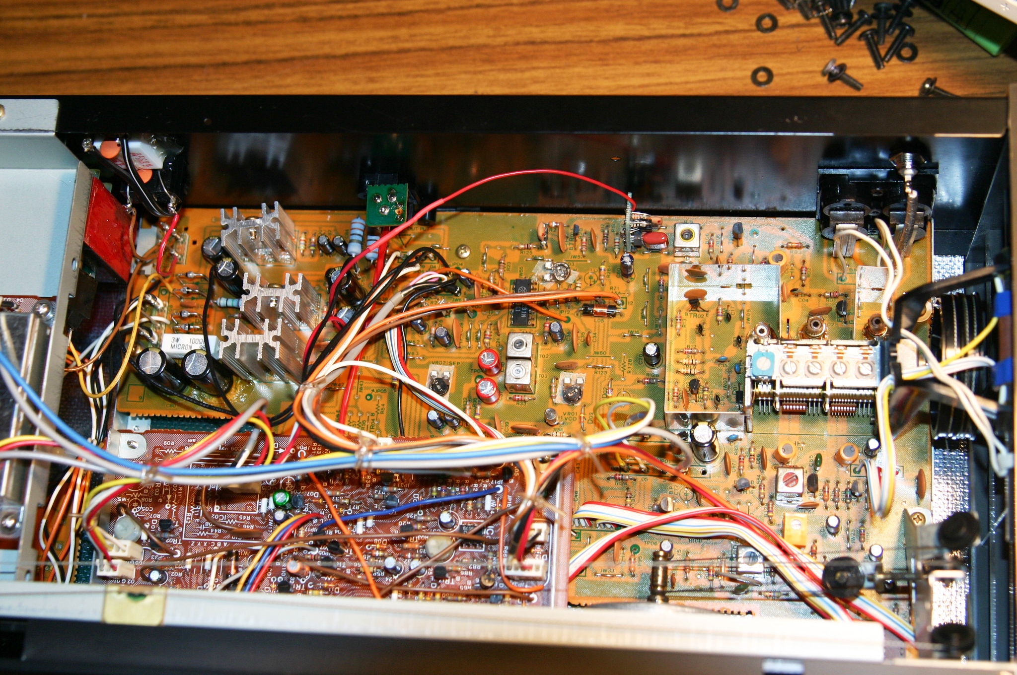